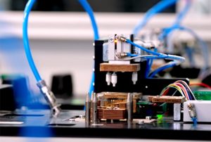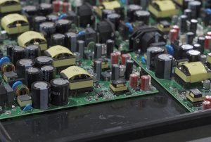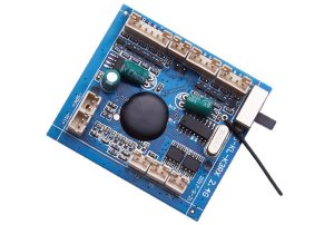

A DC (Direct Current) controller may appear to be a circuit board responsible for power management or load driving. However, its real engineering challenges lie in maintaining stable and reliable operation under voltage fluctuations, changing load conditions, continuous current surges, and complex electromagnetic environments.
Therefore, DC controller PCB assembly requires more than ensuring that components are correctly soldered. Circuit topology, power loop design, thermal management, signal integrity, and manufacturing processes must all be considered as an integrated engineering solution.
1. Core Circuit Architecture Determines the PCB Design Direction
Different DC controllers serve different applications, including DC motor speed regulation, solenoid valve driving, industrial actuators, battery-powered equipment, and DC load management. Their circuit architectures vary depending on the specific application.
A typical DC controller generally consists of the following functional modules:
- Input Protection Circuit: Depending on the input voltage and operating environment, protection features such as reverse polarity protection, TVS transient suppression, overcurrent protection, and input filtering help prevent power abnormalities from affecting downstream circuits.
- Power Driving Circuit: MOSFETs, half-bridge, or H-bridge topologies are selected according to the load characteristics. For DC motor applications requiring forward and reverse rotation, an H-bridge configuration enables current direction reversal.
- Control and Driving Circuit: The MCU handles PWM regulation, logical control, and fault management, while the gate driver controls the rapid switching operation of MOSFETs.
- Current and Voltage Sensing: Shunt resistors, current-sense amplifiers, and voltage feedback circuits monitor operating conditions and provide essential data for closed-loop control and protection strategies.
One detail that is often overlooked is that the current-sensing circuit requires more than an appropriately selected measurement accuracy. The power dissipation, temperature drift, and PCB routing of the sensing resistor also matter. Kelvin four-terminal connections can help minimize the impact of voltage drops across high-current copper traces on measurement accuracy.
2. PCB Layout Priorities: Managing High-Current and Signal Paths
PCB layout for DC controllers should not simply involve placing power components and control components in separate areas. The real priority is managing current paths and their corresponding return paths.
First, minimize power switching loop length. MOSFETs, DC bus capacitors, and associated power components should be positioned carefully to minimize high-frequency switching loop areas, reducing parasitic inductance and voltage spikes.
Second, manage power ground and signal ground. High-current return paths can create ground potential differences, potentially affecting the measurement accuracy of MCUs, ADCs, and sensors. The grounding structure should be designed according to actual current flow to prevent power currents from directly interfering with sensitive signal reference grounds.
Third, optimize copper current-carrying capacity and thermal dissipation. High-current traces must be sized according to continuous current, peak current, copper thickness, allowable temperature rise, and ambient temperature. Adequate thermal copper areas and heat conduction paths should also be provided around MOSFETs, rectifiers, and current-sensing resistors.
Fourth, control switching noise. Gate driver traces should be kept as short as possible. Where necessary, dedicated gate-drive return paths and appropriate gate resistor configurations should be implemented. Coupling between switching nodes and low-level sensing signals must also be considered.
3. DC Controller PCBA Assembly: Soldering Quality Directly Affects Electrical Performance
Unlike ordinary low-power control boards, power control boards involve MOSFETs, power inductors, terminal blocks, and large capacitors, which place higher demands on soldering reliability and assembly consistency.
The manufacturing process requires particular attention to the following areas:
- Stencil and Solder Paste Printing: Optimize stencil apertures according to the pad geometry and thermal pad structures of power components to prevent insufficient solder paste, bridging, or excessive voiding.
- SMT Reflow Soldering: Develop temperature profiles based on PCB thermal capacity, component temperature limitations, and solder paste characteristics to avoid uneven soldering between large components and smaller devices.
- THT Assembly and High-Current Terminals: For connectors, relays, and large power components, control insertion positions, solder joint filling, and mechanical fixation quality.
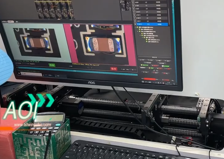
- Solder Joint Inspection: Combine SPI, AOI, and X-Ray inspection where necessary to evaluate solder paste printing, component placement, solder joint conditions, and hidden solder joint quality.
For high-current terminals, mechanical solder joint strength also deserves attention. Vibration, repeated insertion and removal, and cable pulling forces during equipment operation can place continuous mechanical stress on connection points.
4. Testing Beyond Power-On: Verifying Dynamic Load Performance
Functional testing of a DC controller should go beyond basic power-on and switching operations. Meaningful validation requires operating the controller under conditions that closely resemble its actual working environment.
Recommended test items include:
| Test Item | Main Verification Focus |
|---|---|
| Input Voltage Testing | Control stability under different input voltage conditions |
| Load Testing | Performance under rated and peak load conditions |
| Overcurrent and Short-Circuit Protection | Fault response and protection mechanism effectiveness |
| Temperature Rise Testing | Hotspots around MOSFETs, inductors, terminals, and PCB areas |
| PWM and Dynamic Response | Duty cycle variations, sudden load changes, and control response |
| Aging and Continuous Operation | Long-term operating stability and abnormal conditions |
For motor-driven DC controllers, additional testing should cover startup current, stall protection, forward/reverse switching, and braking operations. During motor startup or stall conditions, current consumption can significantly exceed normal operating levels, directly affecting MOSFET selection, copper trace design, and protection thresholds.
5. KingTop Technology: Connecting Control Performance with PCB Manufacturing and PCBA Assembly
KingTop Technology provides PCB manufacturing and PCB assembly services, supporting engineering evaluation, component layout, manufacturing process planning, and electronic assembly according to the application scenario, power rating, structural dimensions, and electrical requirements of DC controllers.
For projects involving high-current driving, compact layouts, or complex control circuits, engineering evaluation should focus on power loop design, thermal structures, component packages, soldering processes, and testing requirements. Identifying potential design and manufacturing risks before mass production helps improve product reliability and manufacturing consistency.
A mature DC controller solution is not simply about making a circuit board power on. It is about controlling current, managing temperature, providing effective fault protection, and ensuring consistent manufacturing quality across every PCBA production batch.