
Robot Toy PCB Assembly Guide: From Motor Control to Reliable Motion Performance. At first glance, a robot toy may seem like a relatively simple consumer electronic product.
However, its internal electronics often integrate multiple functions, including motor control, sensor detection, wireless communication, voice interaction, and battery management. The real challenge in robot toy PCB assembly is not simply soldering components onto a circuit board. It is ensuring that all functional modules work together reliably within limited space while handling motor interference, frequent movement, power fluctuations, and long-term operating stress.
1. Core Circuit Components of Robot Toy PCBA
Different types of robot toys require different circuit configurations, but most designs include several essential functional sections.
Main Controller and Logic Circuit
The main MCU handles motion commands, sensor data acquisition, voice responses, and communication control. During PCB design, engineers need to consider the MCU’s clock frequency, I/O requirements, and peripheral interfaces. Appropriate decoupling capacitors should also be placed near the power pins to minimize transient voltage fluctuations and protect control logic from interference.
Motor Driver Circuit
This is one of the key features that distinguishes robot toy PCBA from ordinary toy control boards. DC gear motors, servos, and stepper motors can generate significant transient currents and electromagnetic interference during startup, stall conditions, and frequent direction changes.
The design should carefully consider driver IC current capacity, power trace width, freewheeling current paths, and thermal performance. Motor current loops should be routed to avoid sharing narrow return paths with sensitive circuits such as MCUs and sensors, reducing voltage disturbances and unexpected control behavior.
Sensors and Interactive Modules
Infrared obstacle detection, ultrasonic ranging, cameras, accelerometers, gyroscopes, and touch sensors determine how effectively a robot can perceive and interact with its surroundings.
Sensitive components such as IMUs should be positioned away from motors and areas exposed to strong mechanical vibration. Wireless modules also require adequate antenna clearance to prevent copper layers, metal structures, and battery placement from degrading RF performance.
Power Supply and Battery Management
Robot toys commonly use rechargeable lithium batteries or disposable batteries. For rechargeable lithium battery designs, the PCB should incorporate appropriate charging management and overcharge, over-discharge, and overcurrent protection circuits.
Engineers must also evaluate voltage drops during motor startup to prevent system resets, communication interruptions, and abnormal sensor readings.
2. PCB Layout and Routing: The Priority Is Interference Control, Not Just Compactness
The internal space of a robot toy is usually restricted by its enclosure, battery compartment, motors, and mechanical transmission structures. PCB layout must therefore be coordinated with the overall mechanical design rather than focusing solely on electrical connectivity.
Several details deserve particular attention:
- Power and control separation: Organize motor drivers, power conversion circuits, MCUs, and sensor circuits into appropriate functional areas. Keep high-current loops short and minimize noise coupling.
- Power integrity: Evaluate the power supply against motor startup current and changing system loads. Add suitable bulk and decoupling capacitors at critical power nodes.
- Signal integrity: Plan I²C, SPI, UART, and PWM routing carefully. Avoid placing sensitive signal traces too close to high-frequency switching nodes and motor output lines.
- Mechanical integration: Confirm screw holes, connector heights, battery positions, antenna orientation, and enclosure clearances early in the design process to prevent mechanical interference after PCB fabrication.
Mechanical vibration is particularly important in moving robots. Connector retention, solder joint strength, PCB support points, and wire harness strain relief should all be considered during design reviews rather than treated as problems to resolve only during final assembly testing.
3. Key Process Controls in SMT Assembly
Robot toy PCBA typically includes chip resistors, capacitors, MCUs, motor driver ICs, sensors, and connectors. Since these components have different package sizes and soldering requirements, the assembly process must be controlled accordingly.
Solder Paste Printing and Component Placement: Fine-pitch ICs and small components require careful control of solder paste coverage, printing alignment, and placement accuracy to prevent insufficient solder, bridging, tombstoning, and component misalignment.
Reflow Soldering Temperature Profile: The temperature profile should be adjusted according to PCB thermal mass, component temperature ratings, and solder paste characteristics to avoid insufficient heating or excessive thermal stress.
Connector and Power Component Soldering: Battery terminals, motor connectors, and switching devices may experience repeated insertion, vibration, or relatively high current loads. Their solder joints should be inspected for proper wetting, mechanical strength, and soldering integrity.
For designs using through-hole terminals, SMT and DIP processes should be scheduled appropriately to ensure that subsequent soldering operations do not affect previously assembled surface-mount components.
4. Testing: Power-On Verification Is Not Enough
Functional testing of robot toy PCBA should closely reflect actual operating conditions. Basic electrical inspection needs to be combined with full functional verification.
| Inspection Method | Main Areas of Focus |
|---|---|
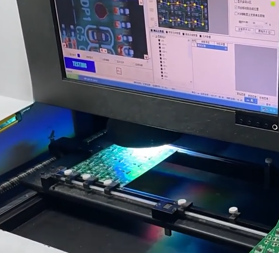
| SPI and AOI Inspection | Solder paste printing, component alignment, polarity, and visible soldering defects |
| X-Ray Inspection | Solder joint quality in applicable component packages with hidden connections |
| ICT Testing | Critical circuit nodes, open circuits, short circuits, and component parameters |
| FCT Functional Testing | MCU operation, motor drive performance, sensors, and wireless communication |
| Aging and Operational Testing | Continuous motion, startup current, temperature rise, and operating stability |
Motor load testing is particularly important. A robot should not pass functional verification based solely on unloaded operation. Testing should also evaluate voltage stability and control response under changing loads, repeated startup and shutdown cycles, and frequent forward-and-reverse movement.
For products featuring voice interaction, wireless connectivity, or vision functions, corresponding module integration tests should also be included. This helps identify problems that may not appear when individual circuit modules are tested separately.
5. Reliability Considerations in Robot Toy PCB Assembly
Robot toys frequently move, turn, collide, and perform repeated mechanical actions. Their reliability therefore cannot be determined by electrical inspection alone.
The following factors deserve particular attention during product development and manufacturing:
- Vibration and Drop Testing: Check whether solder joints, connectors, battery terminals, and PCB mounting structures become loose, damaged, or cracked.
- Thermal Performance and Power Consumption: Monitor temperature changes around motor driver ICs, power converters, and battery charging and discharging circuits.
- ESD Protection: Apply appropriate electrostatic discharge protection to exposed buttons, charging ports, and sensor interfaces.
- Wire Harnesses and Connectors: Prevent repeated robot movement from causing wire tension, bending fatigue, or intermittent electrical contact.
- Safety and Materials: Depending on the target market and intended age group, evaluate battery protection, enclosure construction, and applicable toy safety requirements.
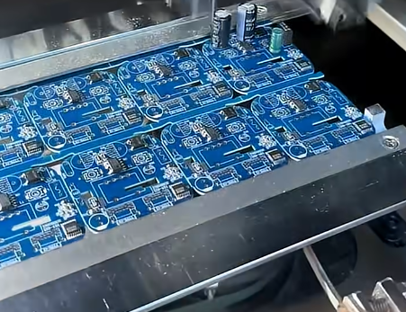
6. KingTop Technology: PCB and PCBA Manufacturing Support for Robot Toys
KingTop Technology provides PCB manufacturing and PCB assembly services, supporting robot toy projects with circuit board production, component placement, soldering inspection, and functional testing requirements.
For robot toys integrating motor control, sensors, and wireless communication, manufacturing quality involves more than placement accuracy. Power component soldering, connector reliability, and complete board-level functional verification are equally important.
Through early-stage DFM reviews and coordinated manufacturing and testing plans, KingTop Technology helps reduce discrepancies between design requirements and production results, supporting a smoother transition from prototype validation to volume manufacturing.
The real value of robot toy PCBA lies in its ability to drive mechanical movements consistently, receive sensor signals accurately, and maintain reliable performance through repeated operation. From circuit layout and SMT assembly to final functional verification, every manufacturing stage should be designed around the robot’s actual motion performance and user experience.