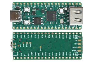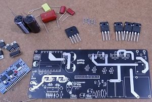

One-Stop PCB Assembly (PCBA) Service Provider for Smart Robotics: Precision Integration from Sensory Perception and Control to Actuation.
The core competitiveness of a smart robot depends not only on its mechanical structure and algorithms but, more importantly, on the ability of its internal electronic systems to work together in a stable and high-speed manner.
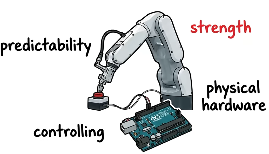
Sensors perceive the environment, the main control board handles decision-making, drive boards manage motors and actuators, and communication modules link the robot to external systems.
All these functions must ultimately be realized through reliable PCBs and PCBA.
Therefore, PCB assembly for smart robots is far more than the simple placement of electronic components; it is a system-level manufacturing process centered on control, power supply, signal transmission, and long-term operational reliability.
Core PCBA Components in Smart Robotics
Circuit architectures vary significantly across different types of robots. While industrial robots, humanoid robots, service robots, and mobile robots have distinct requirements for their PCBA, they generally incorporate the following types of core boards:
Main Control Board: The Electronic Decision-Making Hub
Typically equipped with an MCU, MPU, or embedded processor, the main control board manages motion control, task scheduling, sensor data processing, and communication between various functional modules.
Design considerations focus on processor peripheral circuitry, power integrity, clock stability, and the layout and signal quality of interfaces such as CAN, EtherCAT, UART, and SPI. For multi-axis motion control systems, factors such as real-time control cycles and synchronization across multiple boards must also be addressed.
Motor Drive Board: Handling High-Dynamic Loads
Robot joints, wheel hubs, robotic arms, and grippers generally rely on servo motors, brushless DC (BLDC) motors, or stepper motors. Because drive boards must handle significant transient currents, the layout of power components, the current-carrying capacity of copper traces, thermal management paths, and the precision of current sensing are of critical importance.
In high-power-density designs, the placement of MOSFETs, driver ICs, current-sensing resistors, and bus capacitors must be carefully planned to minimize parasitic inductance and switching noise, ensuring that the power circuitry does not interfere with control signals.
Sensor Interface Boards: Ensuring Accurate Transmission of Perception Data
Vision cameras, LiDAR, IMUs, encoders, torque sensors, and temperature sensors serve as critical perception units for intelligent robots.
PCBA (Printed Circuit Board Assembly) solutions for these components must not only ensure interface compatibility but also address factors such as analog signal interference immunity, differential signal impedance control, grounding strategies, and connector reliability. For instance, high-speed data interfaces for cameras must be properly isolated from motor drive circuitry to minimize the impact of electromagnetic interference (EMI) on image and sensor data.
What Are the Real Challenges in Robotic PCB Assembly?
During operation, robots frequently undergo acceleration, deceleration, and changes in direction, while also being subjected to mechanical shock; furthermore, some equipment must operate continuously for extended periods.
Compared to standard consumer electronics, the manufacturing of PCBAs for robotics requires a much greater focus on dynamic operating conditions.
| Key Area | Critical Technical Control Points |
| PCB Structural Design | Multilayer stack-up, trace width and spacing, impedance control, and power/signal segregation |
| Power Management | Power conversion efficiency, transient response, current-carrying capacity, and power supply noise |
| Precision SMT Assembly | Placement accuracy for BGA, QFN, fine-pitch connectors, and miniature components |
| Power Component Soldering | Solder joint integrity, thermal capacity matching, void ratio, and thermal dissipation design |
| EMI/EMC Protection | Grounding strategy, shielding measures, and high-voltage/low-voltage isolation |
| Mechanical Reliability | Solder joint fatigue, connector retention, vibration and shock resistance |
One factor often overlooked is the mutual interference between the power supply and the signal paths. For instance, the transient current generated when a motor starts can cause fluctuations in the supply voltage; if the power supply design or PCB layout is inadequate, this may lead to the main control board resetting, anomalous sensor data, or even a complete loss of communication.
Consequently, verifying the functionality of a robotic PCBA solely under static conditions is insufficient—testing must also account for actual loads and operational motion states.
From PCB to PCBA: Key Process Controls in Robotic Circuit Board Manufacturing
In the manufacturing of robotic PCBAs, the primary challenge is rarely whether the components can be soldered, but rather whether the integrated functional circuits can maintain stability within a real-world operating environment. For example, does the switching noise generated by motor drives interfere with sensor data acquisition?
Do high-current loads cause localized overheating? Could persistent vibration lead to fatigue in connectors or solder joints? Such issues must be proactively addressed during the manufacturing phase.
| Manufacturing Process | Key Technical Controls for Robot PCBA | Primary Issues Addressed |
| PCB Engineering Design & DFM Review | Review the layout relationships between the main controller, motor drivers, and sensor circuits; evaluate high-current paths, ground return paths, differential impedance, connector positioning, and PCB edge mounting structures | Prevent power supply noise coupling, signal crosstalk, localized overheating, and mechanical interference |
| SMT Assembly & Power Component Soldering | Develop optimized placement and reflow soldering processes for BGA, QFN, MOSFETs, and large connectors; pay particular attention to thermal balance in large copper areas and void formation in power component solder pads | Minimize insufficient solder joints, tombstoning, solder voids, and defects caused by thermal stress |
| Solder Joint Quality & Electrical Inspection | Use SPI to monitor solder paste printing, AOI to inspect component placement and solder joint appearance, and X-Ray to examine BGA and bottom-side solder joints; incorporate ICT to verify critical circuit nodes | Identify hidden soldering defects, incorrect components, polarity errors, and electrical connection problems |
| Motor Driver & Sensor Functional Validation | Test motor drive performance, current sensing, encoder feedback, communication interfaces, and sensor signal responses under actual operating load conditions | Verify normal drive output and feedback signals, and identify abnormalities caused by load variations |
| Mechanical & Environmental Reliability Testing | Conduct thermal, continuous operation, vibration, and connector stability tests based on the robot’s application environment, with particular attention to power components and mechanically stressed areas | Reduce the risk of solder joint fatigue, intermittent connections, and thermal failures during long-term operation |
The key point is this: for robotic PCBA (Printed Circuit Board Assembly), a successful initial power-on is not a sufficient criterion for determining manufacturing quality. This is especially true for motor drive boards and motion control boards; evaluating their actual operational reliability requires a comprehensive assessment that factors in current fluctuations, thermal distribution, signal integrity, and mechanical vibration.
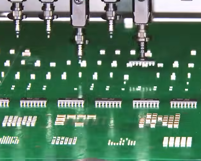
KingTop Technology: PCB and PCBA Manufacturing for Robotic Applications
KingTop Technology specializes in PCB manufacturing and PCB assembly. We provide end-to-end support for intelligent robotics projects, covering everything from PCB fabrication and electronic component assembly to integrated manufacturing solutions.
Whether it is a main control board, a motor drive board, a sensor interface board, or a power management board, each type of board has unique requirements regarding manufacturing precision, component selection, soldering processes, and testing protocols.
Based on your project documentation and specific application needs, KingTop Technology works closely with you to define manufacturing requirements—focusing on critical details ranging from Design for Manufacturing (DFM) to the final quality of the PCB assembly.
For companies developing new robotic products, partnering with a manufacturer that offers integrated PCB and PCBA capabilities helps bridge the gap between design and production, ensuring a smoother transition from engineering prototypes to mass production.
Conclusion
The requirements for electronic manufacturing in the field of intelligent robotics are shifting from simple circuit board fabrication toward multi-board coordination, complex signal processing, and operational reliability under dynamic conditions. A truly robust robotic PCBA must not only perform its intended circuit functions but also withstand the rigors of current surges, continuous operation, mechanical vibration, and complex electromagnetic environments.
KingTop Technology is dedicated to providing comprehensive PCB manufacturing and PCB assembly support, helping to ensure that your robotic electronic systems are manufactured and integrated with the highest level of reliability.