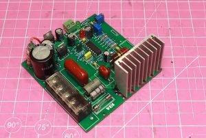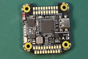

KingTop Technology is a global supplier specializing in high-precision PCB manufacturing and advanced electronic manufacturing services (EMS). As a facility dedicated to motor control PCB assembly, the company provides precision component placement, reliable soldering, and comprehensive quality inspection throughout the entire production process.
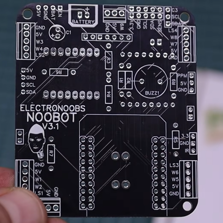
I. Core Value of a Motor Control PCB Assembly Factory
With the rapid development of industrial automation, electric vehicles, smart home appliances, robotics, and new energy equipment, motor control systems are evolving toward higher efficiency, greater precision, miniaturization, and increased intelligence. As the core hardware of a motor controller, the PCB not only facilitates the mounting and electrical interconnection of electronic components but also directly influences control accuracy, power conversion efficiency, electromagnetic compatibility (EMC), and long-term operational reliability.
A professional motor control PCB assembly factory must possess comprehensive capabilities, including coordination with PCB fabrication, electronic component procurement, SMT (Surface Mount Technology) assembly, through-hole component insertion, power device soldering, functional testing, and quality traceability.
Compared to PCB assembly for general electronic products, motor control boards typically involve power switching devices, drive circuitry, current sensing, position sensor interfaces, and multi-channel power management. Consequently, they impose more stringent requirements regarding soldering quality, thermal management design, electrical clearance/creepage distances, and production consistency.
Therefore, selecting a PCB assembly factory with expertise in power electronics manufacturing is a critical step toward enhancing product reliability, shortening R&D cycles, and achieving scalable production.
II. Key Components and Technical Requirements for Motor Control PCBs
The design and assembly approach for a motor control PCB depends on the motor type, operating voltage, output power, and control strategy. Common systems include controllers for brushless DC (BLDC) motors, permanent magnet synchronous motors (PMSM), AC induction motors, and stepper motors.
Main Control and Control Circuitry
The main control circuit typically utilizes an MCU, DSP, or a dedicated motor control processor. It is responsible for executing control algorithms, generating PWM signals, acquiring sensor data, and implementing protection logic.
During the assembly process, critical attention must be paid to the placement accuracy of precision chips, the quality of solder joints, and power integrity. For high-speed control systems, it is also essential to manage potential interference between clock circuits, analog signal paths, and digital circuitry.
Power Drive and Switching Devices
The power stage is a vital component of a motor control board, typically incorporating MOSFETs, IGBTs, gate drivers, and associated protection elements.
During operation, these components can generate significant currents and heat. Manufacturing facilities must select an appropriate soldering process based on component package types, pad structures, and specific manufacturing requirements to ensure that solder joints possess sufficient mechanical strength and reliable electrical connectivity.
For large-format power devices, packages with bottom-side thermal pads, and pads with high thermal capacity, it is also necessary to verify that heat transfer is adequate. This helps prevent issues such as “cold” (incomplete) solder joints, excessive voiding, or localized thermal stress.
Current, Voltage, and Position Sensing Circuits
Components such as current sensors, shunt resistors, voltage sensing circuits, encoder interfaces, and Hall-effect sensor interfaces provide critical feedback for motor control algorithms.
These circuits are typically sensitive to noise and require high measurement accuracy. PCB assembly facilities must strictly control component orientation, soldering quality, and the precise placement of critical components, while collaborating with the design team to verify the consistency of signal acquisition.
Power Management and Protection Circuits
Power management circuits are responsible for providing stable voltage to the main control chip, motor drivers, communication modules, and sensors.
Common protection functions include overcurrent protection, overvoltage protection, undervoltage detection, overtemperature protection, and reverse-polarity protection. Because assembly quality can affect the reliability of these protection mechanisms, critical protection components must be prioritized during inspection and functional testing.
III. Core Manufacturing Processes for Motor Control PCB Assembly
Professional manufacturing facilities typically establish specific process workflows based on product architecture, component packaging, and production volume.
Engineering Review of PCB and BOM
Before production begins, the PCB Gerber files, drill files, Bill of Materials (BOM), component coordinate files, and assembly drawings must be thoroughly reviewed.
Key areas for inspection include component footprints, pad dimensions, polarity markings, component spacing, power trace requirements, and thermal management structures. Additionally, the brand, model, package type, and substitution criteria for critical materials must be verified.
Through Design for Manufacturing (DFM) analysis, potential issues—such as poorly designed pads, insufficient component spacing, or missing test points—can be identified early, thereby reducing the risk of costly rework.
SMT (Surface Mount Technology)
SMT is a primary process in the assembly of motor control PCBs, used for mounting MCUs, driver ICs, resistors, capacitors, and a wide range of other surface-mount components. Typical processes include:
Solder paste printing;
Solder paste inspection (SPI);
High-precision component placement;
Reflow soldering;
Automated Optical Inspection (AOI).
For packages such as fine-pitch chips, QFNs, and BGAs, it is critical to control the volume of solder paste, placement accuracy, and the reflow temperature profile to minimize defects like bridging, insufficient solder, component misalignment, and “cold” (poor) solder joints.
Through-hole Component and Power Device Soldering
Some motor control boards utilize high-current terminals, relays, electrolytic capacitors, connectors, and through-hole power devices, which require through-hole component insertion and corresponding soldering processes.
Depending on the product structure, options include wave soldering, selective soldering, or manual touch-up soldering. For high-current terminals and components with high thermal capacity, particular attention must be paid to solder fill, the shape of the solder joints, and mechanical stability.
For specialized components requiring manual soldering, clear process specifications must be established, and production consistency should be maintained through operator training and in-process inspections.
Cleaning, Conformal Coating, and Protective Treatment
In certain applications, motor control PCBs may be exposed to high humidity, dust, oil, or significant temperature fluctuations over long periods.
Depending on product requirements, processes such as removing flux residue, applying a conformal coating, or localized potting may be necessary. The manufacturing facility must verify material compatibility, coating thickness, coverage areas, and curing conditions to ensure that connector contacts, heat dissipation, and future repairability are not compromised.
Not all motor control boards require cleaning or conformal coating; the specific approach should be determined based on the type of flux used, the product structure, and the operating environment.
IV. Quality Inspection for Motor Control PCB Assembly
Motor control boards typically incorporate both low-voltage control circuitry and high-power drive circuitry. Consequently, quality inspection cannot rely solely on visual checks; it must also encompass electrical testing and functional verification.
Visual and Solder Quality Inspection
Through the use of AOI, microscopic examination, and—where necessary—X-ray inspection, defects such as abnormal solder joints, component misalignment, incorrect polarity, bridging, and issues with hidden solder joints can be identified. For packages with bottom-side pads and complex power devices, the decision to employ X-ray inspection should be based on the specific characteristics of the package and a corresponding risk assessment.
Electrical Testing
Electrical testing may include checks for short circuits and open circuits, measurements of critical power rails, verification of ground continuity, and validation of specific electrical nets.
Depending on the product, In-Circuit Testing (ICT) or flying-probe testing can also be implemented to verify component connections and specific circuit parameters.
Tests such as dielectric withstand (hipot) testing and insulation resistance testing should be determined based on the product’s voltage rating, applicable standards, and design requirements; standardized test parameters should not be applied uniformly across all PCBs.
Motor Control Functional Testing
Functional testing is a critical step in verifying that a motor control PCB meets the requirements of its intended application.
Common test items include:
Power-on startup and power supply stability;
PWM output and control signal verification;
Verification of current and voltage sampling;
Operational status checks for drivers and power stages;
Testing of communication and sensor interfaces;
Verification of overcurrent, overvoltage, and overtemperature protection functions.
Where conditions permit, a test motor or a specialized load can be connected to verify startup, speed control, directional switching, and operational stability.
Production Traceability and Quality Management
A reliable manufacturing facility should have established mechanisms for batch management, material traceability, process documentation, and anomaly handling.
By recording key material batches, soldering parameters, inspection results, and rework history, the root cause of any quality issue can be identified rapidly, while also providing data to support future process optimization.
V. Key Capabilities for a Motor Control PCB Assembly Facility
When selecting a supplier, one should look beyond the quantity of equipment and conduct a comprehensive assessment of their engineering support, manufacturing management, and product verification capabilities.
Component Procurement and Supply Chain Management
Motor control boards incorporate components such as main control chips, power semiconductors, drivers, and precision sampling elements. The facility must maintain compliant procurement channels, robust material inspection processes, and the ability to trace components by batch.
In cases involving discontinued components, long lead times, or unstable supply, the facility should—with client authorization—evaluate potential alternatives, ensuring that no critical materials are substituted without formal approval. 2. Experience in Power Electronics Manufacturing
Manufacturers with experience in power electronics are better equipped to address the unique challenges posed by high-current solder joints, thermal pads, power device packaging, and large copper surface areas.
For high-power controllers, critical factors—such as PCB copper thickness, thermal management structures, connector current-carrying capacity, and insulation design—must be carefully evaluated in collaboration with PCB design and systems engineering teams.
Flexible Production and Delivery Capabilities
The R&D phase typically requires a small number of prototypes for design verification, while mass production focuses on consistency, lead times, and cost control.
An ideal manufacturing partner should be capable of handling everything from prototype fabrication and small-batch runs to full-scale assembly, ensuring stable delivery through standardized operations, robust material management, and rigorous process monitoring.
Engineering Collaboration and Technical Support
High-quality PCB assembly services go beyond simple fabrication based on provided documentation; they also involve identifying potential risks before production begins.
For instance, this may include offering process recommendations for challenging power device soldering, suggesting improvements for testability (e.g., adding test points), or proposing client-approved alternative components to mitigate supply chain lead-time issues.
Such engineering collaboration helps minimize the need for design revisions and manufacturing rework, thereby streamlining the transition from prototype to mass production.
VI. Key Application Areas for Motor Control PCBs
Industrial Automation
Industrial servo drives, variable-frequency drives (VFDs), conveyor systems, and automated production lines require motor control PCBs that offer stable control performance and high resistance to electromagnetic interference.
Electric Vehicles and Powered Equipment
Electric vehicle auxiliary motors, power tools, e-bikes, and other electrically driven equipment demand high power-conversion efficiency, effective thermal management, and operational safety. These applications must also comply with specific industry standards and validation requirements.
Robotics and Intelligent Equipment
Robot joints, mobile robots, and automated actuators typically require compact control board designs that integrate precise speed control, position feedback, communication interfaces, and long-term operational stability.
Smart Home Appliances and HVAC Systems
Motor controllers used in air-conditioning compressors, fans, water pumps, and various smart home appliances must balance energy efficiency, noise levels, cost, and consistency across high-volume production.
New Energy and Industrial Pumps & Valves
In energy storage auxiliary equipment, industrial pumps, fans, and other new energy-related hardware, motor control PCBs must meet specific electrical, thermal management, and reliability requirements tailored to their actual operating environments.
VII. How to Select the Right Motor Control PCB Assembly Manufacturer?
When evaluating potential PCB assembly suppliers for motor control applications, consider the following key aspects:
First, verify engineering capabilities. Ensure the manufacturer can review Gerber files, BOMs, pick-and-place coordinates, and assembly documentation, while identifying potential risks related to the soldering of power components and overall testability.
Second, assess manufacturing processes. Confirm that the available SMT equipment, reflow soldering, selective soldering, AOI (Automated Optical Inspection), and X-ray inspection capabilities align with your project requirements.
Third, define the testing strategy. Establish the scope, standards, and acceptance criteria for visual inspections, electrical testing, functional testing, and reliability verification in advance.
Fourth, evaluate supply chain management.
Confirm the sourcing of critical components, anti-counterfeiting measures, batch traceability, and the approval process for alternative components.
Fifth, review quality management systems. Depending on industry-specific requirements, verify the manufacturer’s quality management system, production records, procedures for handling anomalies, and the validity of relevant certifications.
Sixth, compare total costs. Look beyond the per-unit price; consider engineering fees, the cost of test fixtures, material loss, the risk of rework, lead times, and consistency during mass production.
VIII. From Prototype Validation to Mass Production
Motor control PCB projects typically progress through stages such as prototyping, design validation, process validation, and mass production.
During the prototyping phase, the focus is on verifying circuit functionality, component selection, and control strategies. In the design validation phase, the emphasis shifts to checking temperature rise, performance under load, and protection features. During the process validation phase, the focus is on confirming soldering parameters, test coverage, and production consistency.
Once in mass production, the manufacturer must continuously monitor key process parameters, material changes, and quality data. If anomalies occur, they must conduct root cause analysis, implement corrective actions, and verify the effectiveness of those actions.
For design changes, a version control mechanism must be established to ensure that PCB files, BOMs, firmware versions, and test programs remain synchronized, preventing the accidental mixing of different versions during production.
IX. Conclusion
The core competitiveness of a PCB assembly facility for motor control systems lies not only in its SMT placement and soldering equipment, but also—and more importantly—in its expertise in power electronics manufacturing, engineering collaboration capabilities, quality inspection systems, and supply chain management.
Every stage of the process—from the precision assembly of main control chips and power components to electrical testing, drive function verification, and production traceability—directly influences the performance and reliability of the motor control system.
For manufacturers in sectors such as industrial automation, robotics, electric equipment, and smart home appliances, selecting the right PCB assembly partner helps mitigate manufacturing risks, enhances product consistency, and facilitates the smooth transition of projects from prototype development to full-scale production.
Through rigorous engineering reviews, standardized manufacturing processes, and traceable quality management, a PCB assembly facility for motor control systems can provide stable and reliable electronics manufacturing support tailored to a wide range of applications.