
Guide to Autonomous Electronics Assembly: Intelligent Sensing, Edge Computing, and Hardware Integration.
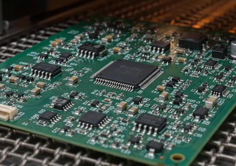
Hardware Architecture of Autonomous Electronic Systems
The primary distinction between autonomous electronic products and traditional electronic devices lies in their capability to go beyond merely executing preset instructions. Instead, they must autonomously perform information acquisition, data processing, state assessment, and motion control in response to changes in their external environment.
For instance, intelligent robots rely on vision sensors, proximity sensors, and motion controllers to perceive their surroundings and execute actions; drones require the coordination of flight control, navigation, power management, and wireless communication modules; and autonomous mobile devices must continuously process data related to localization, obstacle detection, and motion control.
From the perspective of electronics manufacturing, such products typically consist of four core hardware layers:
Sensing Layer: Includes cameras, LiDAR, IMUs (Inertial Measurement Units), as well as temperature and proximity sensors, responsible for capturing data about the external environment and the device’s own state.
Computing Layer: Comprises MCUs, MPUs, GPUs, and FPGAs, which handle data processing, algorithm execution, and real-time task scheduling.
Communication Layer: Includes Ethernet, CAN, USB, and wireless communication modules, facilitating data exchange between various hardware components.
Actuation Layer: Consists of motor drivers, power controllers, and interfaces for actuators, translating computational outputs into physical actions.
These modules are not merely mounted onto a single circuit board; rather, they must be integrated through a well-designed PCB architecture, precise electrical interconnections, and comprehensive system integration to form a stable, collaborative hardware ecosystem.
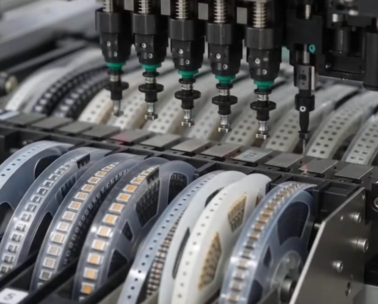
Three Core Engineering Challenges in Autonomous Electronics Assembly
Coordination of Multi-Sensor Signals and High-Speed Data
Autonomous devices frequently process data from multiple sensors simultaneously. These sensors may feature diverse interfaces, voltage levels, sampling frequencies, and data transmission requirements.
For example, a camera might utilize a MIPI interface, an inertial measurement unit (IMU) might employ SPI or I2C, while other control modules might communicate via CAN or Ethernet.
PCB design and assembly must prioritize the following:
- Impedance matching and trace-length control for high-speed differential signals.
- Isolation to prevent interference between analog sensor signals and high-speed digital circuitry.
- Clock synchronization and signal integrity across multiple data interfaces. Connector placement and reliable soldering of high-speed interfaces.
In high-density PCBs, in particular, poor interface placement can increase signal crosstalk and transmission loss, while also complicating system debugging.
Edge Computing and Power Management
Autonomous electronic devices often require local data processing rather than relying entirely on the cloud. Consequently, computing chips, memory, and communication modules impose significant demands in terms of power consumption and heat dissipation.
Engineering design must focus on:
- Power supply stability for processors such as CPUs, GPUs, and FPGAs.
- Isolation and sequencing requirements between multiple voltage rails.
- Ripple, transient response, and power supply noise in DC-DC converters.
- Heat dissipation paths for high-power components and the thermal management structure of the PCB.
- Independent power supply and fault protection for different functional modules.
For compute-intensive devices, it is also necessary to account for processor load fluctuations, transient currents, and temperature rise during long-term operation to prevent system performance degradation caused by unstable power or inadequate thermal management.
Control Systems and Actuator Interfaces
Autonomous electronic products must not only process data but also drive physical mechanical equipment.
For instance, a robot control board must interface with servo motors, encoders, and drivers, while unmanned systems require the management of motors, servos, and other actuators.
Therefore, PCB assembly must prioritize the soldering quality of power components, the layout of drive circuitry, protection against back-electromotive force (back-EMF), current sensing, and electrical isolation.
For high-current actuator interfaces, careful attention must be paid to copper foil thickness, pad dimensions, the current-carrying capacity of connectors, and thermal management structures.
From PCB Assembly to System-Level Hardware Integration
The manufacturing challenges for autonomous electronic products lie not merely in whether an individual PCB functions correctly, but in whether various electronic modules can operate reliably in tandem within a real-world environment.
In actual manufacturing projects, focus can be placed on the following aspects:
| Engineering Stage | Key Technical Requirements |
| Hardware Architecture Design | Functional module partitioning, signal path planning, and PCB stack-up optimization |
| Core Component Integration | Compatibility of AI processors, sensors, memory chips, and power management components |
| High-Density Circuit Assembly | Precision BGA and QFN placement, fine-pitch soldering, and solder joint quality control |
| Data and Interface Connectivity | High-speed differential signaling, CAN, Ethernet, and connector reliability |
| Power and Thermal Design | Current load assessment, power component heat dissipation, and temperature rise control |
| System-Level Functional Validation | Multi-sensor coordination, communication stability, control response, and full-system integration testing |
It is important to note that the proper functioning of an individual PCB does not guarantee the stable operation of an entire autonomous electronic system.
In practical applications, issues such as power supply interference, communication timing discrepancies, signal incompatibility, and control response delays can arise between different hardware modules.
For instance, a sensor might perform correctly during isolated testing, yet produce anomalous data once integrated into the main control system—often due to power supply noise or a mismatch in interface timing.
Consequently, once an electronic product has been assembled, it must undergo cross-module interface testing, data exchange verification, and comprehensive system-level operational testing to ensure that the sensing, computing, and execution components function together reliably.
Assembly Requirements for Various Autonomous Devices
Given the significant differences in operating modes and hardware architectures across various products, PCB assembly strategies cannot be governed by a single, uniform set of standards.
| Product Type | Core Electronic Modules | Assembly Priorities |
| Autonomous Mobile Robots | MCU, LiDAR, IMU, Motor Drivers | Multi-sensor interfaces and motion control |
| Unmanned Aerial Vehicle (UAV) Systems | Flight Controller, GNSS, IMU, ESC | Lightweight design, vibration resistance, and power management |
| Autonomous Driving Equipment | AI Processors, Cameras, Radar Interfaces | High-speed data transmission and thermal management |
| Intelligent Industrial Equipment | PLC, FPGA, Communication Modules | Industrial communication and long-term operational stability |
| Autonomous Inspection Equipment | Image Processors, Sensors, Data Acquisition Modules | Signal integrity and measurement accuracy |
For equipment intended for long-term operation or deployment in complex environments, verification protocols—covering vibration, temperature cycling, electromagnetic compatibility (EMC), and electrical safety—should be developed based on the specific application.
How can the manufacturing quality of indigenous electronic products be verified?
Quality verification for indigenous electronic products should encompass everything from soldering quality to electrical performance and system operational status.
In addition to standard inspections such as AOI (Automated Optical Inspection), X-ray, and ICT (In-Circuit Testing), specialized tests tailored to the product’s actual functions should also be designed.
| Test Item | Key Validation Criteria |
| AOI Inspection | Component placement, polarity, and solder joint appearance |
| X-Ray Inspection | Hidden solder joint quality of BGA and QFN components |
| ICT Testing | Open circuits, short circuits, and key electrical parameters |
| Power Integrity Testing | Voltage ripple, load variations, and power supply stability |
| Communication Interface Testing | CAN, Ethernet, USB, and high-speed interfaces |
| Functional Testing (FCT) | Sensor data acquisition, data processing, and control output |
| Environmental Reliability Testing | Temperature variations, mechanical vibration, and long-term operational stability |
For devices incorporating AI processors and complex sensors, high-load operational testing can also be conducted to evaluate processor temperature rise, power supply stability, and the system’s ability to sustain continuous operation.
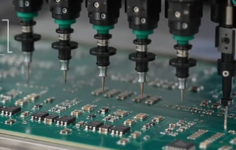
KingTop Technology: A Partner for PCB Assembly in Autonomous Electronic Products
KingTop Technology specializes in PCB assembly and electronic manufacturing services (EMS), providing support for smart hardware, industrial controls, robotics, and other customized electronic products.
Based on a client’s product architecture and technical specifications, the company offers a comprehensive suite of services, including PCB fabrication, component procurement, SMT (Surface Mount Technology) assembly, DIP (Dual In-line Package) insertion, precision soldering, functional testing, and final electronic product assembly.
Addressing the specific requirements of autonomous electronic devices—such as high-density circuit design, multi-interface integration, complex component packaging, and power management—KingTop Technology emphasizes the synergy between engineering evaluation and manufacturing processes. Through DFM (Design for Manufacturing) analysis, rigorous production process control, and quality inspection, the company assists clients in transitioning seamlessly from PCB prototyping to mass production.
Whether for robotics control boards, drone electronic modules, smart sensors, or industrial edge computing devices, tailored PCB assembly and electronic manufacturing solutions can be developed to meet specific project requirements.
Future Trends in the Manufacturing of Autonomous Electronics
Driven by advancements in AI computing, edge intelligence, and multi-sensor fusion, autonomous devices are evolving toward higher integration, lower power consumption, and more compact hardware architectures.
The future of electronic assembly will focus on three key areas:
High-Density Integration: Enhancing hardware integration within limited space through the use of HDI (High-Density Interconnect) PCBs, advanced packaging, and modular design.
Intelligent Hardware Synergy: Creating tighter system architectures that integrate computing, sensing, communication, and actuation modules.
Reliability-Oriented Manufacturing: Integrating engineering design, material selection, manufacturing processes, and system verification to minimize hardware failures during actual deployment.
The competitiveness of autonomous electronic products depends not only on algorithms and computational power but also on the design quality and manufacturing reliability of the underlying electronic hardware.
An excellent PCB assembly solution ensures that complex electronic modules can operate in a stable, continuous, and coordinated manner within real-world environments.
Conclusion
From intelligent sensing and autonomous decision-making to precise execution, electronic hardware serves as the fundamental bedrock for the operation of any autonomous system. Selecting a manufacturing partner with capabilities in engineering support, precision PCB assembly, and system testing helps improve product development efficiency and the reliability of the final product.