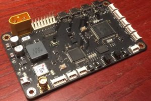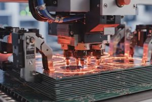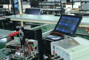

Industrial control systems typically require long-term, continuous operation while being subjected to electrical interference, temperature fluctuations, mechanical vibrations, and complex operating environments.
As the core electronic substrate for industrial control equipment, a rigid PCB not only facilitates the electrical interconnection of components but also directly influences control precision, signal stability, and the operational lifespan of the equipment.
Consequently, the assembly of rigid PCBs for industrial control systems requires systematic control across various aspects—including circuit design, material selection, component layout, soldering processes, and reliability testing—rather than focusing solely on standard SMT (Surface Mount Technology) placement and solder quality.
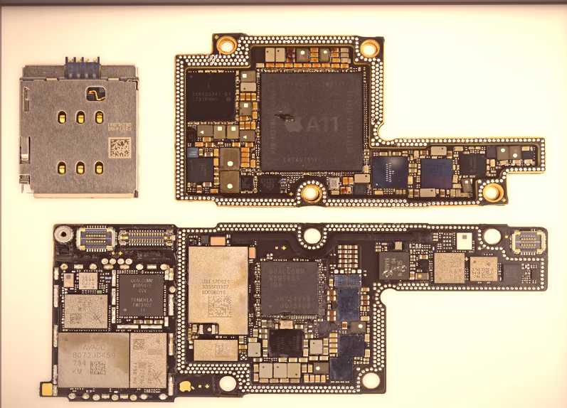
I. Why Are Rigid PCBs Used in Industrial Control Systems?
Rigid PCBs offer structural stability, high mechanical strength, excellent dimensional precision, and suitability for multi-layer circuit designs. These characteristics enable them to meet the rigorous demands of industrial control equipment, which requires both long-term operational reliability and the integration of complex circuitry.
Typical applications include:
- PLC Controllers: Facilitating digital and analog input/output (I/O) and logic control.
- Industrial Inverters: Supporting power drive, current sampling, and motor control.
- Servo Drives: Enabling high-speed signal transmission and precise motion control.
- Industrial Power Modules: Handling voltage conversion, power management, and overcurrent protection.
- Automated Control Equipment: Integrating sensor interfaces, communication modules, and control circuitry for actuators.
Different devices impose varying requirements on PCBs—such as current-carrying capacity, insulation performance, signal integrity, and thermal dissipation—necessitating designs tailored to specific applications.
II. Key Design Requirements for Industrial Control Rigid PCBs
PCB Material and Layer Stack-up Design
For industrial control PCBs, the choice of materials and the number of layers are determined based on factors such as operating temperature, voltage levels, mechanical strength, and signal complexity.
Common materials include standard FR-4, high-Tg (glass transition temperature) FR-4, and copper-clad laminates with specialized electrical properties.
For control equipment that operates at high temperatures over extended periods, high-Tg materials help enhance the PCB’s dimensional stability and reliability under thermal stress. In complex control circuits, a multi-layer PCB allows for the strategic allocation of power planes, ground planes, digital signal layers, and analog signal layers.
Power and Signal Integrity Design
Industrial control equipment typically incorporates both high-voltage, high-current power circuits and low-level control signals.
Key design considerations include:
- Carefully planning power loops and grounding structures to minimize interference caused by common impedance.
- Optimizing the layout of analog and digital signals to reduce noise coupling.
- Controlling the impedance of high-speed communication lines to ensure signal transmission quality.
- Evaluating the current-carrying capacity and temperature rise of power components and high-current traces.
- Implementing appropriate ESD, surge, and overvoltage protection circuits at critical interfaces.
In equipment such as variable-frequency drives (VFDs) and servo drives, high-frequency noise generated by power switching can interfere with control signals; therefore, PCB layout and electromagnetic compatibility (EMC) design must be addressed concurrently.
III. Core Manufacturing Processes for Rigid PCB Assembly
Industrial control PCB assembly requires not only reliable solder joints but also ensures that various types of components remain stable under complex operating conditions.
Typical Assembly Process Flow
| No. | Assembly Process |
| 01 | Incoming PCB Inspection |
| 02 | Solder Paste Printing |
| 03 | SMT Component Placement |
| 04 | Reflow Soldering |
| 05 | DIP Insertion and Wave Soldering |
| 06 | AOI and X-Ray Inspection |
| 07 | Electrical and Functional Testing |
| 08 | Final Inspection and Packaging |
SMT (Surface Mount Technology) Process
Components such as microcontrollers, driver ICs, communication ICs, resistors, capacitors, and MOSFETs are typically mounted using the SMT process.
Key parameters to control include solder paste thickness, printing alignment, placement accuracy, and the reflow soldering temperature profile. For components with packages like QFN or BGA, special attention must be paid to pad design, solder voiding rates, and the quality of hidden solder joints.
DIP (Dual In-line Package) Assembly and Power Component Soldering
Industrial control PCBs often incorporate connectors, relays, transformers, electrolytic capacitors, and various high-power components.
These components may be assembled using through-hole (DIP) mounting, selective wave soldering, or manual soldering. For high-current terminals and power connection points, it is essential to verify solder joint fill, wetting, mechanical stability, and the impact of thermal stress from the soldering process.
Thermal Management and Structural Assembly
Industrial control equipment frequently operates under load for extended periods, which can cause components like MOSFETs, IGBTs, and power management ICs to generate significant heat.
During assembly, it is crucial to ensure effective thermal contact between heat sinks, thermal interface materials (pads), and power components. Furthermore, component height, spacing, and mounting methods must be carefully managed to prevent mechanical stress from compromising solder joints or the structural integrity of the PCB.
IV. Quality Inspection and Reliability Verification for Industrial Control PCBs
The quality of an industrial control PCB cannot be determined solely through visual inspection; it must be verified by evaluating electrical performance, soldering quality, and behavior under actual operating conditions.
| Inspection Item | Main Verification Criteria |
| Solder Joint and Assembly Quality Inspection | Soldering integrity of high-current pads, connectors, relays, and power components |
| Power Supply Stability Testing | Input voltage range, output ripple, voltage accuracy, and load regulation |
| Analog Signal Acquisition Testing | ADC sampling accuracy, signal linearity, and input channel consistency |
| Digital I/O Testing | Digital input/output performance, logic-level compatibility, and channel response |
| Communication Interface Testing | Data transmission and communication stability of RS-485, CAN, Ethernet, and other interfaces |
| Power Driver Testing | MOSFET and IGBT drive waveforms, switching response, and load capability |
| Thermal Performance Testing | Temperature rise of critical components, localized hotspots, and thermal stability under continuous load |
| EMC Immunity Testing | Operating performance under electrostatic discharge (ESD), electrical fast transient (EFT), and surge interference |
For high-reliability industrial control equipment, additional testing—such as burn-in testing, damp-heat testing, and long-term load operation testing—may be incorporated based on specific product application requirements.
Regarding quality standards, criteria such as IPC-A-610 and IPC J-STD-001 can be referenced, depending on the product grade and customer specifications. It should be noted that inspection items and acceptance criteria must be determined based on the actual application; not all industrial PCBs require the same inspection protocol.
V. Technical Issues Often Overlooked in Industrial Control PCB Assembly
In practical projects, certain PCB assembly defects may not manifest during initial power-on, but rather emerge gradually after long-term operation.
Particular attention should be paid to the following:
Mechanical Stress on Large Components
Components such as relays, transformers, large capacitors, and connectors are susceptible to mechanical stress in environments subject to vibration. Risks of failure can be mitigated through optimized component placement, structural securing, and robust solder joint design.
Soldering and Heat Dissipation for Power Components
The soldering quality of components like MOSFETs and IGBTs directly impacts thermal conductivity. Issues such as voids in bottom-side pads, insufficient solder, or inadequate thermal design can lead to abnormal localized temperature increases.
Protection Against Moisture and Contamination
In industrial environments exposed to dust, humidity, or corrosive gases, the application of a conformal coating or other protective measures may be necessary. Care must be taken to precisely control the coating coverage, ensuring that connectors, test points, and heat-dissipation areas remain unaffected.
Traceability of Materials and Production Batches
Industrial control equipment typically features a long product lifecycle. Consequently, it is essential to establish mechanisms for BOM version control, component batch recording, production process documentation, and test data traceability to mitigate risks during future maintenance or mass production.
VI. KingTop Technology: Industrial Control PCB Assembly and Manufacturing Services
PCB Manufacturing, SMT Assembly, DIP (Through-hole) Assembly, and Complete PCBA System Integration
Founded in 2004, KingTop Technology specializes in PCB manufacturing and PCBA electronic assembly services, providing comprehensive electronic manufacturing solutions for sectors including industrial control, automotive electronics, telecommunications equipment, and medical electronics. The company provides a one-stop service, ranging from PCB design support, circuit board fabrication, and component procurement to SMT/DIP assembly, quality inspection, and final product assembly.
For industrial control projects, KingTop Technology emphasizes the synergy between PCB design and actual manufacturing processes. Through DFM (Design for Manufacturing) engineering assessments, soldering process control, and inspection methods—such as AOI, X-Ray, ICT, and FCT—the company helps clients enhance both manufacturing consistency and operational reliability.
Tailored PCB fabrication and assembly solutions can be developed based on specific technical requirements, accommodating industrial control circuit boards with varying structures, power ratings, and production volumes.
Official Website: https://king-top.com/
VII. Conclusion
In industrial control systems, the core objective of rigid PCB assembly extends beyond mere component placement and circuit interconnection; it encompasses the comprehensive management of electrical performance, thermal regulation, mechanical reliability, and manufacturing consistency.
Every stage—from initial PCB design and material selection to SMT/DIP assembly, quality inspection, and functional verification—must be optimized with the equipment’s actual operating environment in mind.
Partnering with a manufacturer that possesses integrated capabilities in PCB fabrication, component procurement, assembly, and testing helps mitigate engineering development risks and ensures the long-term operational stability of industrial control electronics.