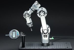
Intelligent robots are evolving from traditional industrial assembly lines into diverse application scenarios characterized by high complexity, space constraints, and dynamic environments—such as humanoid robots, medical surgical robots, micro-drones, and equipment for extreme environment exploration.
In these highly integrated systems, internal electronic and electrical architectures face unprecedented dual challenges regarding space and reliability.
Traditional interconnect solutions—relying on ribbon cables, connectors, and discrete rigid circuit boards (FR-4 PCBs)—are not only bulky and heavy but also highly prone to failures like poor contact or cable breakage caused by the high-frequency movement of joints and intense vibrations.
Against this backdrop, the deep integration of multilayer PCB and Rigid-Flex technology has emerged as a key breakthrough in the field of custom robot electronics design.
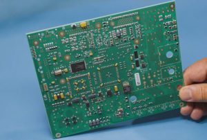
Rigid-flex boards perfectly combine the structural support and routing capabilities of rigid PCBs with the bendability and 3D routing characteristics of flexible printed circuits (FPCs). This eliminates the need for numerous board-to-board connectors, significantly improving internal space utilization and the overall mechanical lifespan of the robotic system.
Comprehensive control over the entire lifecycle—from initial design, material science, and precision manufacturing to final assembly—of rigid-flex multilayer PCBs for custom robots has become a key benchmark for evaluating capabilities in robotic electronic hardware R&D and manufacturing.
I. Core Value of Multilayer PCB and Rigid-Flex Technology in Robotics
High Standards for Robotic Circuit Boards
Modern custom robots integrate a vast array of sensors, microprocessors, servo drives, and communication modules. Internal space is often extremely limited, particularly in areas such as joints, robotic arm end-effectors, and the head.
These components require circuit boards that not only offer high integration density to accommodate multilayer routing but also withstand frequent dynamic bending, continuous mechanical vibration, wide operating temperature ranges, and electromagnetic interference (EMI).
Traditional rigid boards often lead to bulky structural designs because they cannot accommodate three-dimensional folding, whereas purely flexible boards lack the mechanical rigidity required to support large chips and heat-dissipating components. Consequently, rigid-flex multilayer circuit boards emerged as a solution, perfectly balancing the structural support strength of rigid sections with the dynamic 3D routing capabilities of flexible sections.
Definition and Technical Advantages of Rigid-Flex PCBs
A rigid-flex PCB is formed by laminating rigid circuit boards (Rigid PCBs) and flexible circuit boards (FPCs) together according to design specifications, creating a single printed circuit board with integrated electrical connectivity.
Its core advantages include: First, it significantly reduces the number of connectors and solder joints in the system, thereby lowering failure rates caused by increased contact resistance, oxidation, or vibration-induced disconnections, and substantially extending the robot’s Mean Time Between Failures (MTBF). Second, rigid-flex PCBs enable true 3D spatial routing; they can be precisely “cut” and bent to fit the robot’s internal structure, drastically reducing the device’s overall volume and weight—a critical factor for load-sensitive mobile robots or biomimetic humanoid robots. Finally, they optimize signal transmission paths, reduce parasitic capacitance and inductance, and enhance high-speed digital signal integrity.
Necessity of Multilayer Board Structures in Complex Robotic Joints and Control Systems
Complex robotic control systems must handle intricate power distribution networks (PDNs), high-speed differential buses (such as EtherCAT, CAN bus, and MIPI), and sensitive analog sensor signals.
This necessitates the use of multilayer board structures (e.g., 4, 6, 8, or even more layers). By incorporating dedicated ground planes (GND planes) and power planes, these structures provide excellent electromagnetic shielding and stable reference impedance. In rigid-flex circuit board design, rigid sections typically house core components—such as main control chips, FPGAs, and power management ICs—and provide space for multi-layer routing. Meanwhile, flexible sections span across joints or pivot points to facilitate signal transmission between areas; a multi-layer flexible structure enables complex power and signal separation within confined spaces, ensuring stable electrical performance during high-speed robotic operation.
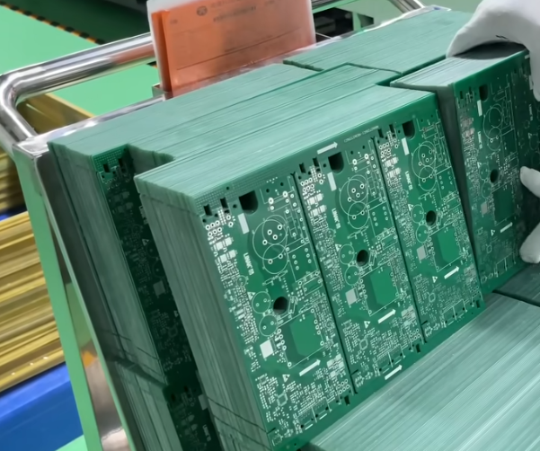
II. Design and Material Selection for Custom Robotic Rigid-Flex PCBs
Substrate Selection: PI, FR-4, and Performance Matching
Material selection for rigid-flex boards directly determines the finished product’s electrical performance and mechanical lifespan.
Rigid sections typically utilize high-Tg (glass transition temperature) FR-4 epoxy glass-cloth laminates to ensure dimensional stability and warp resistance during high-temperature soldering and mechanical stress.
Flexible sections primarily use polyimide (PI) film as the substrate, chosen for its excellent heat resistance, extremely low dielectric constant, superior flexibility, and high mechanical strength.
When selecting between adhesive-based and adhesive-less substrates, applications involving high-frequency robotic bending should prioritize adhesive-less double-sided or single-sided PI substrates; this minimizes thickness and rigidity while preventing adhesive layer cracking during bending.
Additionally, the choice of coverlay or flexible solder mask ink must be compatible to ensure no delamination occurs in dynamic bending zones.
Stack-up Design Strategy and Impedance Control
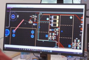
Rigid-flex PCB stack-up design is a complex engineering task that relies heavily on engineer experience, requiring a balance between rigid section thickness, flexible section layer count, impedance matching, and mechanical symmetry. The stack-up design should adhere to symmetry principles to prevent board warping or twisting caused by uneven thermal stress during the lamination process.
Impedance Control: For high-speed serial buses within the robot (such as USB 3.0, Ethernet, or MIPI camera signals), strict characteristic impedance calculations (typically 50-ohm single-ended or 100-ohm differential) are required for microstrip or stripline traces in both rigid and flexible zones.
Rigid-Flex Transition: The interface between rigid and flexible sections is a high-risk area for stress concentration. Designs must avoid abrupt changes in dielectric thickness; instead, stepped stack-up or beveled transition designs should be employed to allow for the gradual release of stress.
Bending Zone Design and Mechanical Reliability Considerations
Flexible zones in robots often undergo long-term dynamic bending (e.g., at joints). When designing the bend radius, industry standards must be strictly followed: for single-layer flexible boards, the static bend radius is typically no less than 10–15 times the board thickness, while the dynamic bend radius should exceed 100 times the thickness; requirements for multi-layer flexible boards are even more stringent.
Trace Routing Direction: Conductors in flexible zones must be routed perpendicular to the bending axis. Long-distance routing parallel to the axis or 90-degree right-angle routing within the bending zone is strictly prohibited; arc transitions (teardrop designs) should be used instead.
Copper Foil Design: Copper foil in flexible zones should ideally feature a balanced, symmetrical grid or solid copper pattern. Additionally, conductors in multi-layer flexible boards should utilize staggered routing to prevent stress accumulation along the same vertical axis.
Routing Specifications and Electromagnetic Compatibility (EMC/EMI) Design
Internal components such as motor drivers and switching power supplies generate strong electromagnetic radiation, whereas low-voltage signal lines—such as those for chassis sensors—are highly sensitive. In the design of rigid-flex PCBs, robust EMC protection measures must be implemented:
Shielding Layer Design: Incorporate a shielding layer (shielding film) over the flexible sections or critical signal layers, grounding it via conductive silver paste or rolled copper mesh to create a complete Faraday cage, thereby effectively suppressing electromagnetic leakage and crosstalk.
Ground Loop Optimization: Ensure that digital, analog, and power grounds are tied together at appropriate locations—using either single-point or multi-point grounding—to prevent ground bounce noise from interfering with sensor data acquisition accuracy.
III. Manufacturing Process Flow for Rigid-Flex Multilayer PCBs
Inner-Layer Circuit Fabrication and Lamination Technology
The manufacturing process for rigid-flex multilayer boards is far more complex than that for traditional rigid boards. The process begins with inner-layer pattern transfer, etching, and AOI (Automated Optical Inspection) on the copper-clad laminates designated for the rigid and flexible zones.
During the lamination stage, precise control of process parameters is critical due to the significant differences in curing temperatures and coefficients of thermal expansion (CTE) between the rigid materials (FR-4) and flexible materials (PI). Precise temperature control profiles and staged pressure control must be employed, utilizing specialized prepregs or thermoplastic adhesive films to ensure a tight bond at the rigid-flex interface—free from bubbles, delamination, or adhesive overflow.
Laser Drilling, Blind/Buried Vias (HDI), and Plating Processes
To achieve the high-density miniaturization required for robotics PCBs, multilayer boards typically utilize HDI (High-Density Interconnect) technology. UV or CO2 lasers are used to precisely drill microvias in the rigid zones and at the rigid-flex transition areas, enabling high-density electrical interconnection between layers.
Following laser drilling, a rigorous desmear process is required to remove residual resin debris from the via walls. Subsequently, electroless copper plating and electrolytic copper plating are performed to ensure the thickness and uniformity of the copper layer on the via walls, thereby guaranteeing the reliability of the via metallization under conditions of high current and thermal shock.
Separation of Rigid and Flexible Zones and Cutting Control
Once all lamination, plating, and surface finishing processes are complete, the individual boards must be separated from the larger panel. Because the physical properties of the rigid and flexible materials differ drastically, conventional mechanical milling can easily cause tearing of the copper foil or the formation of burrs in the flexible zones. Consequently, modern high-end manufacturing typically employs hybrid processing techniques: first, a CNC router mills the contours of the rigid sections; then, a high-precision UV or green laser cutting machine performs fine-profile cutting and window opening on the flexible sections, ensuring smooth edges and dimensional accuracy.
Surface Finish Processes and Their Suitability for Robotic Environments
The surface finish directly impacts the reliability of subsequent component soldering and the circuit board’s corrosion resistance in harsh environments. Common surface finish processes include:
ENIG (Electroless Nickel Immersion Gold): Offers excellent flatness, making it ideal for fine-pitch component soldering and gold wire bonding; its superior oxidation resistance makes it the preferred choice for robot control boards.
OSP (Organic Solderability Preservative): Features a flat surface and low cost but offers limited thermal cycling resistance; it is rarely used for robot joint mainboards subject to high thermal vibration.
Immersion Silver / Immersion Tin: Provide good electrical conductivity but are prone to migration or discoloration in high-humidity or sulfur-rich environments, necessitating the use of protective coatings.
IV. Precision Assembly and Soldering Processes for Custom Robot Circuit Boards
Component Selection and High-Density Surface Mount Technology (SMT) Challenges
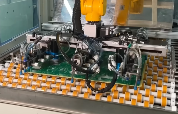
Custom robot circuit boards often feature a dense arrangement of fine-pitch packaged chips—such as BGA, QFN, and CSP—alongside high-power MOSFETs, inductors, and various precision sensors. Because rigid-flex boards lack absolute rigid support near their flexible zones, they are susceptible to slight deformation during SMT processing, particularly on conveyor belts or during heating cycles.
Therefore, high-precision, custom-designed carriers (or pallets) are essential on the SMT production line. These carriers securely hold the rigid-flex board flat, preventing gaps between the stencil and the PCB that could otherwise lead to solder paste printing defects (such as solder bridging or insufficient solder).
Precision Assembly of Irregular Components, Sensors, and Connectors
Robot systems incorporate numerous sensors linked to mechanical structures—such as Hall sensors, encoders, and inertial measurement units (IMUs)—as well as custom connectors. The assembly of these irregularly shaped components often cannot be fully accomplished by standard SMT placement machines; it requires fine-tuning via high-precision vision positioning systems, or even partial manual soldering or automated selective soldering.
Positioning accuracy must be strictly controlled during assembly to ensure that the relative positional error between the sensor and the robot’s mechanical axis remains within the micrometer range; otherwise, the robot’s motion control precision will be directly compromised.
Soldering Process Control: Reflow Soldering, Selective Wave Soldering, and Underfill
Reflow Soldering: For surface-mount components, the temperature profile must be optimized based on the characteristics of lead-free solder paste (e.g., SAC305). This ensures gradual temperature ramp rates across the preheat, soak, reflow, and cooling zones, preventing thermal shock that could cause multilayer board delamination or internal micro-cracks in components.
Underfill: For robot joint control boards subject to high vibration, underfill adhesive must be dispensed and cured beneath BGA and CSP chips. This underfill material evenly distributes thermomechanical stress between the chip and the PCB, significantly enhancing resistance to drops and high-frequency vibration.
Conformal Coating and Protection Processes (Dust, Water, and Shock Resistance)
Robots frequently operate in extreme environments—outdoors, on factory floors, or even underwater, as well as in areas with high humidity or heavy dust. Once circuit board assembly is complete, rigorous conformal coating must be applied.
Automated spraying or brushing processes are typically used to apply a uniform layer of acrylic, polyurethane, or silicone conformal coating over the board surface, effectively blocking moisture, salt spray, dust, and chemical corrosion.
For critical rigid-flex transition areas and connector plugs, structural adhesive is also applied for mechanical reinforcement to prevent fatigue fractures caused by the robot’s vigorous movements.
V. Quality Control and Testing/Verification of Robot Circuit Boards
Electrical Performance Testing: Flying Probe Testing and In-Circuit Testing (ICT)
To ensure the absolute integrity of electrical connections on every custom rigid-flex robot circuit board, a rigorous testing process must be implemented. For small-batch, high-mix customized robot circuit boards, Flying Probe Testing eliminates the need for dedicated fixtures, allowing for precise detection of open circuits, short circuits, and component values (such as resistance and capacitance) directly based on CAD netlists.
For mass production, In-Circuit Testing (ICT) and Functional Testing (FCT) fixtures are employed. These simulate the robot’s input and output signals under actual operating conditions to perform comprehensive, automated functional verification of sensor responses, motor control PWM outputs, communication bus handshake protocols, and more.
Mechanical Stress and Environmental Reliability Testing
Before the design is finalized, robot circuit boards must undergo rigorous Environmental Stress Screening (ESS):
High/Low-Temperature Cycling (Thermal Shock): Evaluates the ability of the board material, solder joints, and components to withstand thermal stress caused by extreme, rapid temperature fluctuations.
Vibration and Shock Testing: Simulates multi-dimensional mechanical vibrations—such as those generated by a robot walking, running, colliding, or during the high-speed start/stop of robotic arms—to verify the fatigue resistance of rigid-flex transition zones and solder joints.
Salt Spray and Damp-Heat Testing: Verifies the long-term protective performance of conformal coatings in high-temperature, high-humidity, and corrosive environments.
Signal Integrity (SI) and Power Integrity (PI) Testing
Using high-bandwidth digital storage oscilloscopes, network analyzers, and eye-diagram testers, signal integrity tests are conducted on high-speed signals (such as Ethernet and high-speed differential sensor signals) to evaluate metrics like jitter, attenuation, and crosstalk. Simultaneously, dynamic impedance testing is performed on power planes to ensure that voltage droop remains within safe margins during sudden, high-current surges.
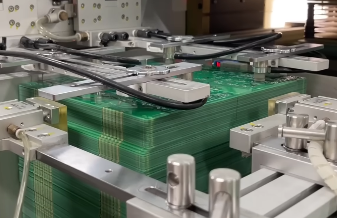
VI. Summary
The rigid-flex integration and assembly of customized multi-layer robot circuit boards constitute a systems engineering process that combines cutting-edge materials science, complex 3D structural design, advanced PCB manufacturing techniques, and precision electronic assembly. As robots evolve toward higher integration, lighter weight, and greater environmental adaptability, rigid-flex technology not only resolves industry pain points—such as cluttered cabling, space constraints, and poor reliability—but also imbues modern robots with unparalleled flexibility and vitality.
From initial layer stack-up planning and impedance simulation to laser drilling, lamination control, precision SMT assembly, and conformal coating, every stage demands rigorous professional expertise from R&D and manufacturing teams.
Leveraging deep technical expertise, advanced intelligent manufacturing facilities, and a stringent quality management system, KingTop Technology has established itself as a global leader in providing rigid-flex circuit board and assembly services for robots.
KingTop Technology specializes in delivering “one-stop” turnkey solutions for medical robots, industrial automation, humanoid robots, and high-end intelligent equipment. These solutions encompass everything from initial design and multi-layer rigid-flex PCB manufacturing to high-density component assembly and comprehensive reliability testing.
Backed by a top-tier engineering R&D team and world-class manufacturing equipment, the company successfully overcomes technical challenges related to miniaturization, high-speed performance, and vibration resistance in robotic electronics, empowering global clients to create next-generation intelligent robots that deliver superior performance and reliability.