
As energy storage systems continue to evolve toward larger capacities, intelligent operation, and higher levels of integration, the Energy Management System (EMS) has become a critical control unit for coordinating energy storage operations.
The EMS controller is typically responsible for data acquisition, equipment communication, operational strategy execution, power coordination, and system status monitoring. The quality of its hardware assembly directly affects the operational stability and control reliability of the entire energy storage system.
Compared with conventional consumer electronics, PCB assembly for energy storage EMS controllers must not only meet precision electronic assembly requirements but also address long-term operational stability in industrial environments, communication reliability, power integrity, and electromagnetic compatibility (EMC) performance.
Hardware Composition and Assembly Characteristics of Energy Storage EMS Controllers
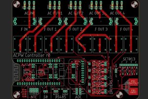
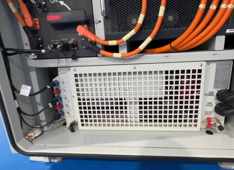
An energy storage EMS controller typically consists of a main control processor, power management module, communication interfaces, data acquisition circuits, digital input/output circuits, and peripheral control circuits.
Among these components, the main control module executes control logic and operational strategies. The communication module handles data exchange with the Battery Management System (BMS), Power Conversion System (PCS), electricity meters, and upper-level monitoring systems. The power module provides stable power supplies for individual functional units, while the input/output circuits collect equipment status information and execute control commands.
From a PCB assembly perspective, EMS controllers have the following characteristics:
- Mixed Assembly of Multiple Component Types: The assembly involves MCUs, memory devices, communication chips, isolators, power management ICs, connectors, and various passive components, requiring high precision in SMT placement and soldering consistency.
- Integration of Power and Signal Circuits: Different functional areas have different requirements for soldering quality, electrical connections, and insulation design. Particular attention must be paid to the assembly quality of power interfaces, signal interfaces, and isolation areas.
- Complex Communication Interfaces: Common interfaces include CAN, RS485, and Ethernet. Some designs also incorporate optocouplers, digital isolators, and interface protection components.
- High Requirements for Long-Term Operation: Energy storage equipment typically operates continuously for extended periods. Therefore, component soldering reliability, connector stability, and overall PCB assembly consistency are particularly important.
Core PCB Assembly Processes for Energy Storage EMS Controllers
EMS controller PCBA manufacturing requires a comprehensive process control system covering everything from incoming material inspection to final functional verification, ensuring effective quality control throughout every production stage.
IQC Incoming Quality Control
Before production, incoming inspections must be performed on bare PCBs, electronic components, and auxiliary materials.
Key inspection items include PCB appearance, pad quality, surface finish condition, board material batches, and solderability. Component models, specifications, package types, batches, and Moisture Sensitivity Levels (MSL) must also be verified to prevent incorrect components, mixed materials, or moisture-damaged components from entering production.
Solder Paste Printing and SPI Inspection
Solder paste printing is a critical process affecting SMT soldering quality. Appropriate stencil aperture designs and printing parameters should be selected according to the PCB pad structure and component package characteristics.
Solder Paste Inspection (SPI) equipment is used to measure solder paste thickness, volume, area, and printing offset. Particular attention should be given to fine-pitch ICs, QFN packages, and other high-density pad areas to reduce the risk of insufficient solder paste, excessive solder paste, and solder bridging.
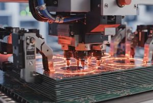
Precision SMT Component Placement
Automated component placement is performed according to the EMS controller BOM and PCB coordinate files.
For MCUs, communication chips, memory devices, power management ICs, and precision passive components, placement position, angle, polarity, and orientation must be carefully controlled. For fine-pitch packages, placement parameters should be optimized based on equipment accuracy, component package characteristics, and PCB pad design.
Reflow Soldering
Reflow soldering is a critical process for forming reliable solder joints. An appropriate temperature profile should be developed according to PCB thickness, copper distribution, component thermal capacity, and solder paste material characteristics.
Key parameters include preheating, soaking, peak temperature, and Time Above Liquidus (TAL). Insufficient temperature must be avoided to prevent cold solder joints, while excessive thermal stress should also be controlled to prevent component damage or PCB deformation.
AOI and X-Ray Inspection
After reflow soldering, Automated Optical Inspection (AOI) is used to detect component misalignment, reversed polarity, missing components, incorrect components, and soldering appearance defects.
For packages such as BGA, where solder joints cannot be directly inspected through conventional optical methods, X-Ray inspection can be used according to product risk assessments and inspection requirements to examine solder joint connections, voids, bridging, and other defects.
DIP Through-Hole Assembly and Selective Soldering
For EMS controllers using through-hole components, such as large connectors, terminal blocks, relays, and certain power components, DIP insertion and soldering processes must be arranged according to the product structure.
For mixed-technology PCBs, the production sequence of SMT and THT assembly should be properly planned. Wave soldering, selective soldering, or manual soldering may be selected according to component structures and thermal sensitivity to ensure proper solder wetting without damaging surrounding components.
Key Quality Control Requirements for EMS Controller PCBA
EMS controllers are connected to multiple critical devices within energy storage systems. Quality control must therefore go beyond visual inspection and incorporate comprehensive verification of product functionality, electrical performance, and actual operating conditions.
Soldering Reliability
Key inspection areas include fine-pitch ICs, connectors, power components, and BGA packages. Defects such as cold solder joints, solder bridging, insufficient solder, and abnormal solder joints must be effectively controlled.
Power Supply and Electrical Performance
Inspect power inputs, regulated outputs, protection circuits, and critical test points to verify power supply stability and circuit connection integrity. For different voltage levels or isolation circuits, corresponding insulation and dielectric withstand tests must be performed in accordance with product design requirements and applicable standards.
Communication Interface Reliability
Necessary communication tests should be performed on CAN, RS485, Ethernet, and other interfaces. These tests should verify data transmission and reception, interface protection circuits, and communication stability to ensure that the EMS controller can communicate properly with related energy storage system equipment.
EMC and Anti-Interference Performance
Energy storage systems contain switching power supplies, power conversion equipment, and complex electromagnetic environments. Therefore, assembly quality must be carefully controlled for shielding components, grounding connections, interface protection devices, and filter components. Corresponding EMC verification should also be conducted in combination with the overall equipment design.
Environmental Adaptability and Long-Term Stability
According to product application requirements, verification tests should include high- and low-temperature testing, temperature cycling, damp heat testing, and vibration testing. Where necessary, aging and operational tests should also be conducted to evaluate PCBA stability under the target operating conditions.
Functional Testing of Energy Storage EMS Controller PCBA
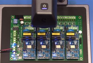
After assembly and visual inspection, functional verification should be performed according to the product testing specifications to prevent products with normal soldering appearance but abnormal circuit functionality from entering the final equipment assembly stage.
The main testing items include:
- Power-On Testing: Check power input, regulated voltage outputs, and startup status.
- Main Controller Functional Testing: Verify MCU startup, program execution, memory read/write operations, and critical control logic.
- Communication Testing: Verify data transmission and reception capabilities through CAN, RS485, Ethernet, and other interfaces.
- Input/Output Testing: Inspect digital inputs, relay outputs, and analog signal acquisition functions.
- Protection Function Testing: Verify power protection, abnormal condition detection, and fault feedback logic according to design requirements.
- System Integration Testing: Connect the EMS controller to the corresponding test environment and simulate data communication between the EMS and devices such as BMS and PCS.
For products requiring firmware programming, a traceability relationship should also be established between firmware versions, programming records, and test results to ensure consistency between hardware and software versions.
Development Requirements for Energy Storage EMS Controller PCB Assembly Manufacturing
As energy storage systems demand higher levels of safety, operational efficiency, and intelligence, EMS controller PCBA manufacturing is evolving from conventional SMT processing toward precision manufacturing, automation, and comprehensive traceability.
A qualified PCBA manufacturer must not only have SMT placement, DIP insertion, reflow soldering, and automated inspection capabilities but also establish comprehensive process documentation, quality management systems, and product traceability mechanisms.
From a practical manufacturing perspective, the core quality of an energy storage EMS controller does not depend on any single production process. Instead, it relies on the coordinated management of component control, soldering processes, inspection and verification, and comprehensive production quality control.
Only by implementing quality requirements throughout the entire process, including incoming materials, assembly, inspection, and functional verification, can manufacturers continuously improve product consistency and long-term operational reliability.
Therefore, PCB assembly manufacturing for energy storage EMS controllers should be based on precision SMT processes, prioritize electrical performance and communication functionality verification, and rely on reliability testing and production data management to provide a dependable electronic manufacturing foundation for the stable operation of energy storage systems.