
Building Control Systems That Meet the Demands of Real-World Robotics. Robot circuit design involves much more than simply connecting a microcontroller, motor drivers, and sensors.
During operation, robots are exposed to fluctuating current loads, electromagnetic interference, mechanical vibration, and heat. Poor design in any of these areas can lead to control instability, communication interruptions, or even complete system shutdowns.
A reliable robot PCBA solution must address control logic, motor drive circuits, sensor feedback, power management, and manufacturing reliability. Every part of the system must work together to ensure stable performance under demanding operating conditions.
1. Robot Electronic Architecture: Understanding How the Modules Work Together
The electronic architecture varies depending on the type of robot. For example, service robots place greater emphasis on sensor integration and motion control, industrial robots require precise real-time control, while mobile robots need particular attention to motor driving, battery management, and wireless communication.
A typical robot control system consists of several core electronic modules:
- Main Control Unit: Uses an MCU, MPU, or embedded processor to manage motion planning, task execution, data processing, and coordination between different modules.
- Motor Drive Unit: Uses MOSFETs, gate drivers, and current-sensing circuits to control DC motors, BLDC motors, or servo motors.
- Sensor Interfaces: Connects encoders, IMUs, ultrasonic sensors, infrared sensors, LiDAR, and vision modules to collect real-time operating data.
- Power Management Unit: Converts battery input into different voltage levels to provide stable power for the main controller, motor drivers, and sensors.
- Communication Interfaces: Supports CAN, RS485, UART, SPI, I²C, or Ethernet, depending on system requirements, enabling data exchange between control boards.
The objective is not simply to make each module work independently. More importantly, the entire electronic system must remain stable when multiple modules operate simultaneously.
2. Critical Considerations in Robot PCB Design
2.1 Separate Power Circuits from Control Circuits
Motor startup, acceleration, and emergency stops can cause substantial current fluctuations. Improper PCB layout between power circuits and sensitive signal traces may result in ground bounce, supply voltage fluctuations, and signal interference.
High-power sections, such as motor drivers and power conversion circuits, should be physically separated from sensitive areas containing MCUs, sensors, and analog sampling circuits whenever practical.
For high-current paths, trace width must be determined according to operating current, copper thickness, temperature rise, and allowable voltage drop rather than relying solely on general design experience.
2.2 Motor Driving and Feedback Sampling
Motor control is not just about delivering sufficient power. Accurate feedback is equally important.
The placement of current-sensing resistors, sampling loop length, gate driver routing, and connections between power devices can all affect control stability.
For precision motor control methods such as Field-Oriented Control (FOC), designers should also pay attention to current sampling timing, ADC sampling noise, and power-ground return paths.
2.3 Sensor Signal Integrity
Encoders, IMUs, and other sensors are particularly sensitive to electrical noise. PCB design should incorporate appropriate filtering, ESD protection, and shielding where necessary, depending on the interface and operating environment.
For CAN, RS485, and other high-speed differential interfaces, impedance matching, differential pair routing, termination resistors, and continuous reference planes must also be considered to minimize communication errors during robot operation.
2.4 Thermal Management and Mechanical Integration
Motor drive MOSFETs, DC-DC power ICs, and high-current connectors are often the main heat sources on robot control boards.
Engineers need to evaluate component power dissipation, copper heat-spreading areas, thermal vias, and temperature distribution across the PCB.
Mechanical compatibility is equally important. PCB dimensions, connector orientation, mounting holes, and cable exit positions must all match the robot’s mechanical structure. Circuit design should never be treated as an isolated engineering task separate from overall system integration.
3. From Circuit Schematic to PCBA: What Matters During Manufacturing?
Once the circuit architecture and schematic are completed, engineering validation and manufacturing processes must translate the design into a reliable, production-ready PCBA.
| Manufacturing Stage | Key Control Points |
|---|---|
| DFM Engineering Review | Check component footprints, pad design, component spacing, manufacturability, and assembly clearances |
| SMT Assembly | Maintain precise placement of fine-pitch ICs, BGA, QFN, and miniature passive components |
| Reflow Soldering | Optimize temperature profiles according to component temperature limits and PCB construction to prevent insufficient soldering, bridging, and tombstoning |
| Solder Joint Inspection | Use AOI and X-Ray inspection where appropriate to identify visible and hidden solder joint defects |
| Functional Testing | Verify power supply operation, communication, motor driving, sensor acquisition, and protection functions |
| System-Level Integration | Evaluate compatibility between the control board, motors, sensors, batteries, and wiring harnesses |
One particularly important point is that functional testing should go beyond simply checking whether the board powers on.
Testing should also simulate motor startup, load variations, continuous operation, and abnormal power interruptions. The objective is to monitor power stability, temperature rise, and communication performance under realistic operating conditions.
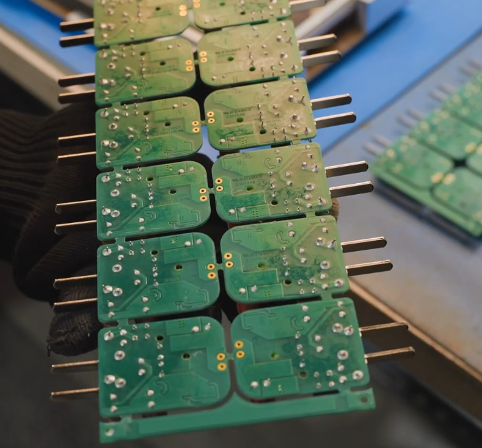
4. KingTop Technology: From PCB Manufacturing to PCB Assembly
KingTop Technology specializes in PCB manufacturing and PCB assembly, supporting projects involving robot control boards and related electronic modules through PCB engineering reviews, manufacturing, and circuit board assembly.
For robotic PCBA projects, the connection between design and manufacturing is especially important. For example, whether high-current copper areas are suitable for fabrication, whether connector placement facilitates final system assembly, and whether BGA and QFN components can be properly inspected all influence production efficiency and overall product reliability.
KingTop Technology focuses on integrating PCB manufacturing requirements with PCB assembly considerations, helping customers move from circuit board design to practical production while reducing engineering and manufacturing coordination challenges.
5. Conclusion
The real challenge in robot circuit design is not simply getting a control board to function. It is ensuring that the board continues to operate reliably under changing motor loads, complex sensor environments, and prolonged operating conditions.
From power architecture and power circuit layout to signal integrity, PCBA soldering quality, and system-level functional validation, every engineering detail contributes to the robot’s overall control performance.
For robotic product development, reliability must be built into the electronic design from the beginning, rather than addressed only after problems emerge during system testing.