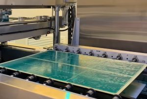
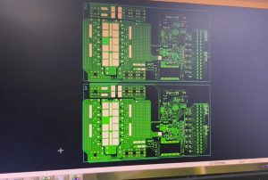
Gain an in-depth understanding of the drone flight controller PCB assembly process—covering MCUs, IMUs, SMT (Surface Mount Technology) assembly, precision soldering, AOI (Automated Optical Inspection), X-ray inspection, electrical testing, and reliability verification—to help drone R&D and manufacturing companies optimize their PCBA production quality.
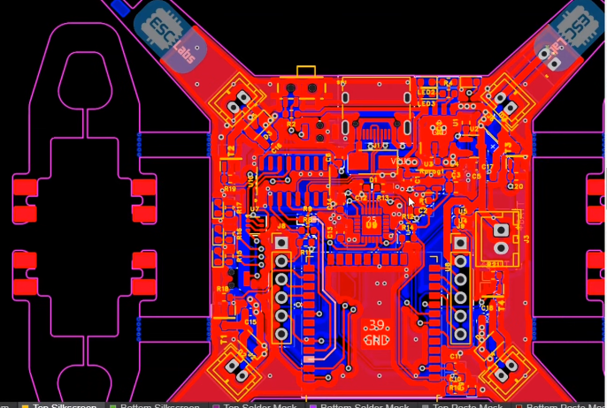
I. The Drone Flight Controller: The Core Electronic System Determining Flight Stability
The application scenarios for drones have expanded far beyond traditional aerial photography to include industrial inspection, agricultural crop protection, surveying and exploration, logistics and transport, emergency rescue, and intelligent robotics.
At the heart of these applications lies the flight controller (FC). The assembly of the flight controller PCB is the critical manufacturing stage that transforms the flight control system design into a reliable hardware product.
A drone flight controller PCB is more than just a collection of microcontrollers, sensors, and connectors soldered onto a circuit board. It requires the integration of real-time computing, attitude sensing, power management, signal communication, and interfaces for external peripherals—all within a limited space—while meeting stringent reliability requirements for operation in complex environments characterized by vibration, temperature fluctuations, electromagnetic interference, and long-term continuous use.
For drone manufacturers, high-quality PCB assembly is not only vital to the stability of the flight control system, but it also directly impacts product consistency, R&D cycles, manufacturing costs, and the efficiency of long-term maintenance.
Consequently, every stage—from PCB design and component procurement to SMT assembly, precision soldering, functional testing, and full-system verification—requires careful planning and rigorous control.
II. Core Hardware Architecture of a Drone Flight Controller PCB
Flight controller boards typically employ a highly integrated electronic hardware architecture. While specific drone models may vary in terms of processor performance, the number of sensors, communication interfaces, and power supply design, they generally share a common set of functional modules.
Main Processor and Real-Time Computing Unit
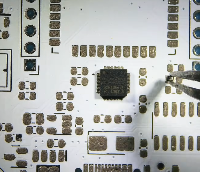
The microcontroller (MCU) serves as the central processing unit of the flight controller. It is responsible for collecting sensor data, executing control algorithms, managing communication interfaces, and handling real-time tasks in accordance with the system design specifications. During the PCB assembly process, the main control chip is typically housed in various package types, such as QFN, LQFP, or BGA. The package type, pad dimensions, pin pitch, and thermal design requirements directly influence the soldering process and inspection methods.
For chips with high pin density, it is critical to control solder paste printing quality, placement accuracy, and the reflow soldering temperature profile. For packages with hidden solder joints (e.g., those located underneath the component), the necessity of X-ray inspection should be evaluated based on product requirements.
The main control chip generally requires the placement of peripheral components, including clock circuits, decoupling capacitors, debugging interfaces, and other essential auxiliary circuitry. A well-planned component layout minimizes signal path lengths and provides a foundation for stable operation and subsequent debugging.
Inertial Measurement Unit (IMU)
An Inertial Measurement Unit (IMU) typically integrates a gyroscope and an accelerometer; some configurations may incorporate additional inertial sensing functions to capture motion data, such as the angular velocity and acceleration of an aircraft.
IMUs are sensitive to mechanical vibration, mounting orientation, soldering-induced stress, and the surrounding electrical environment. During PCB design and assembly, it is essential to minimize unnecessary mechanical stress and ensure that the sensor’s mounting position and orientation strictly adhere to design specifications.
If the flight control board requires high stability in attitude measurement, one must consider a holistic approach—encompassing sensor placement, structural mounting methods, vibration-dampening design, and the overall vibration characteristics of the system—rather than relying solely on the performance specifications of an individual component.
Barometer, Magnetometer, and Positioning Interfaces
A barometer provides data on atmospheric pressure changes, which assists in altitude estimation; a magnetometer offers a reference for heading estimation; and a GNSS interface facilitates the connection of an external satellite positioning module.
When designing the PCB for these components or interfaces, factors such as power supply noise, the distribution of heat sources, the placement of magnetic components, and electromagnetic compatibility (EMC) requirements for antennas and RF signals must be taken into account.
Notably, magnetometers are susceptible to interference from current loops, magnetic components, and external magnetic fields. In the final product, performance should be verified by considering the hardware layout, calibration procedures, and the operating environment of the complete system.
Power Management and Communication Interfaces
Flight control boards typically incorporate voltage regulation circuits, power filtering, overcurrent protection, and multiple voltage domains to supply power to the main control chip, sensors, and communication modules.
Common communication interfaces include UART, SPI, I²C, CAN, and USB; the specific configuration depends on the flight control architecture and the requirements of the peripheral devices.
During the PCB assembly process, the soldering quality of power management ICs, power components, connectors, and protection devices is of critical importance. For high-current power paths, careful attention must also be paid to the current-carrying capacity of copper traces, pad design, thermal management paths, and the mechanical strength of connectors.
III. PCB Design and Manufacturing Preparation: Laying the Foundation for High-Quality Assembly
The manufacturing quality of a flight control board begins to take shape well before formal production commences. The more comprehensive the PCB design files, Bill of Materials (BOM), and assembly requirements, the lower the likelihood of encountering issues during the production process.
Multilayer PCBs and High-Density Layouts
Modern flight control boards often require the integration of various high-speed digital components, sensitive analog sensors, and power management circuits within a limited footprint. Depending on the complexity of the product, a multilayer PCB structure may be employed to achieve more efficient signal routing, power distribution, and grounding design.
During the design phase, factors such as impedance control, return paths, ground plane integrity, crosstalk, and power integrity must be thoroughly evaluated. For high-speed interfaces and clock networks, routing rules should be established based on specific signal requirements.
It is important to note that a higher number of layers does not necessarily equate to better performance. The optimal PCB stack-up, routing strategy, and manufacturing tolerances should be determined by balancing circuit complexity, size constraints, cost, and reliability requirements.
BOM and Design for Manufacturing (DFM) Review
The Bill of Materials (BOM) serves as a vital reference for PCB assembly. It should typically include manufacturer part numbers, component specifications, package information, quantities, and any restrictions regarding alternative components.
Prior to mass production, the manufacturer should verify the consistency between the BOM and the Gerber files, drill files, pick-and-place (centroid) files, and assembly drawings. For critical chips, sensors, and power components, it is also necessary to verify supply channels, product lifecycles, batch traceability requirements, and approval protocols for alternative parts.
Conducting Design for Manufacturing (DFM) and Design for Testability (DFT) reviews early in the process helps identify potential issues—such as pad design, component spacing, test point placement, and assembly orientation—thereby reducing the need for rework during the trial production phase.
IV. SMT Assembly: Precision Assembly for High-Density Flight Control Circuits
Surface Mount Technology (SMT) is a core process in the PCB assembly of drone flight control boards. Manufacturing quality depends on the coordinated control of several stages, including solder paste printing, component placement, reflow soldering, and in-process inspection.
Solder Paste Printing
At the start of production, an appropriate stencil is selected based on the PCB pad design and component package requirements. Solder paste is then deposited uniformly onto the designated pads using printing equipment.
For fine-pitch chips and high-density components, careful attention must be paid to the volume of solder paste deposited, positional accuracy, stencil aperture design, and the risk of bridging between pads.
Where necessary, Solder Paste Inspection (SPI) equipment can be used to verify the printing results, allowing for the timely detection of issues such as insufficient or excessive solder, misalignment, or missing deposits.
High-Precision Component Placement
Using coordinate files and component package data, an automated pick-and-place machine mounts components—including MCUs, IMUs, memory modules, passive components (resistors/capacitors), and others—onto their designated locations.
For flight control boards, placement precision is critical; it affects not only electrical connectivity but also component orientation, the consistency of sensor installation, and the outcomes of subsequent testing.
Before production begins, the origin point, rotation angle, component polarity, and package orientation defined in the coordinate files must be verified, and a “first-article inspection” should be performed to confirm the accuracy of the placement program.
Reflow Soldering and Thermal Process Control
Once components are placed, the PCB proceeds to the reflow soldering stage. Under a controlled temperature profile, the solder paste undergoes preheating, soaking, reflow, and cooling phases to form reliable solder joints. Reflow soldering temperature profiles must be developed based on solder paste technical specifications, the thermal capacity of the PCB, and the temperature tolerance of the components, rather than by simply applying a fixed set of temperature parameters.
For boards with significant variations in thermal capacity, careful attention should be paid to the temperature distribution across different areas of the board to prevent localized issues such as insufficient soldering or overheating.
Following the reflow process, inspections should be conducted to check for solder joint appearance, component misalignment, “tombstoning,” bridging, and other visible defects. For specific package types and critical connections, additional evaluation methods—such as X-ray inspection—may be employed.
V. Assembly Control for Special Packages and Critical Components
Flight control boards often incorporate components that are small in size, feature fine-pitch leads, or are highly sensitive to the soldering environment; therefore, specific process control measures must be established for each package type.
QFN and BGA Packages
QFN packages offer a small footprint, with some models featuring a thermal pad on the underside, while BGA packages rely on an array of solder balls on the bottom to establish electrical connections. While these packages enable higher levels of integration, they also increase the complexity of solder joint inspection and rework.
During assembly, particular focus should be placed on solder paste volume, component alignment, the reflow profile, and pad design.
For components with hidden solder joints, appropriate inspection methods should be selected based on quality risk assessments and product requirements. While X-ray inspection can help identify certain soldering anomalies, it cannot replace comprehensive electrical testing and functional verification.
Sensors and Precision Analog Circuits
The soldering quality of IMUs, barometers, and other sensitive components must be evaluated in the context of their mounting location, mechanical structure, and exposure to thermal stress.
Certain sensors are highly sensitive to board flexure, localized stress, or proximity to heat sources; consequently, an optimal layout must be determined during the design phase, and unnecessary mechanical handling should be avoided.
If protective coatings (conformal coatings) are used, their compatibility with the components, connectors, and sensor apertures must be verified to ensure that sensitive areas are not inadvertently covered.
Connectors and Mechanical Solder Joint Strength
Flight control boards are typically equipped with connectors for power, debugging, and peripheral modules. Unlike miniature components that rely solely on solder joints for attachment, connectors—which may be subject to frequent mating/unmating cycles or mechanical strain from cables—require additional consideration regarding their mechanical anchoring strength. During the design and manufacturing process, verify the connector orientation, mounting height, pad configuration, and assembly space, and conduct the necessary mechanical checks in accordance with product requirements.
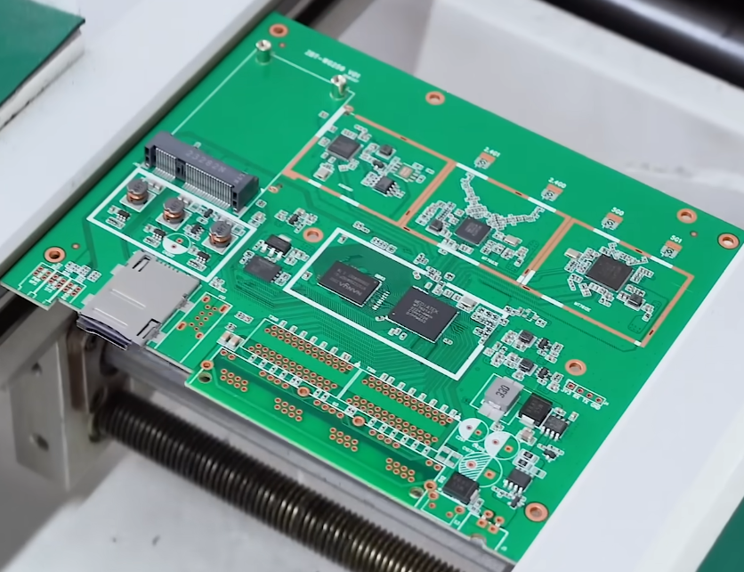
VI. PCBA Quality Inspection: From Solder Joint Examination to Electrical Verification
PCB assembly does not mark the end of the production process. Only through rigorous inspection and verification can it be determined whether a flight control board meets the established quality requirements.
Automated Optical Inspection (AOI)
Automated Optical Inspection (AOI) utilizes a vision system to examine visible solder joints and the status of components. It can identify issues such as component misalignment, polarity errors, missing components, solder bridges, and certain other soldering defects.
While AOI is well-suited for process control in SMT (Surface Mount Technology) assembly, it has limitations when it comes to inspecting hidden solder joints, such as those found under BGA (Ball Grid Array) components. Therefore, AOI results alone are insufficient to conclude that an entire flight control board is free of soldering defects.
X-Ray Inspection
For components like BGAs, bottom-terminated devices, and other packages with hidden solder joints, X-ray inspection may be employed based on a risk assessment.
This method allows for the examination of solder ball connections, void distribution, and certain internal soldering anomalies. However, final assessments must also take into account the specific package structure, acceptance criteria, and data from other inspection methods.
ICT and Flying Probe Testing
In-Circuit Testing (ICT) and flying probe testing—supported by appropriate test design—can be used to verify electrical connections, check for short circuits or open circuits, and measure component parameters.
The choice between these methods depends on factors such as test point layout, fixture costs, production volume, and circuit complexity. For small-batch R&D projects, flying probe testing often offers greater flexibility, whereas for high-volume production—where mature test fixtures are available—ICT may provide higher testing efficiency.
Functional Testing and Firmware Verification
Flight control boards must undergo functional testing to confirm that core functions—such as the startup of the main control chip, power output, communication interfaces, and sensor connectivity—are operating correctly.
Where appropriate test conditions exist, further verification can be performed on firmware flashing, debugging interfaces, sensor data acquisition, and system self-test functions.
Test results should be documented to ensure traceability, facilitating root-cause analysis of defects, the validation of process improvements, and the management of consistency across mass-produced units.
VII. Reliability and Environmental Adaptability of Drone Flight Control Boards
The operating environment for drones is inherently complex. High-frequency vibration, temperature fluctuations, humidity, dust, and electromagnetic interference can all impact electronic systems. Consequently, the reliability of a flight control board must be ensured through a multi-layered approach encompassing design, manufacturing, and comprehensive system-level verification.
Vibration and Mechanical Stress
Drone motors, propellers, and airframe structures can generate mechanical vibrations at various frequencies. Prolonged exposure to vibration may increase the risk of fatigue in connectors, solder joints, and mechanical mounting structures.
During the design phase, it is essential to evaluate PCB mounting methods, connector placement, and necessary vibration-dampening measures in the context of the airframe structure. For critical applications, vibration testing protocols should be developed based on product risk profiles and intended operating environments.
Temperature and Thermal Management
Main control chips, power management components, and power devices generate heat during operation. Effective thermal management—achieved through optimized copper foil design, grounding structures, thermal pads, and heat dissipation paths—helps regulate the operating temperatures of these components.
During production, it must be ensured that the temperature tolerance of the components aligns with the soldering process. For products with specified operating temperature ranges, appropriate temperature cycling or environmental testing should also be conducted.
Moisture/Dust Protection and Surface Coating
For applications such as agricultural spraying or outdoor inspection, the need for conformal coatings, sealed enclosures, or other protective measures should be assessed based on the specific operating environment.
It is important to note that coatings and seals cannot serve as a substitute for sound PCB design and robust process control. Factors such as material compatibility, heat dissipation, ease of connector maintenance, and the integrity of sensor measurement paths must all be considered in a comprehensive evaluation.
Electromagnetic Compatibility (EMC) and Power Integrity
Electromagnetic coupling can occur between the flight control board and components such as motor drivers, wireless communication equipment, or other electronic modules. Implementing proper power filtering, grounding strategies, signal return paths, and interface protection helps mitigate these risks.
The final performance must be validated through rigorous electrical testing, system integration, and real-world operational verification.
VIII. From Prototyping to Mass Production: Establishing a Complete Manufacturing Workflow
For drone developers, an ideal PCB assembly partner should offer more than just SMT (Surface Mount Technology) production capabilities; they should also be able to support the transition from R&D prototypes to stable, large-scale mass production. A typical manufacturing process includes:
Engineering Review: Verifying Gerber files, BOMs (Bill of Materials), pick-and-place coordinates, assembly drawings, and any special process requirements.
Material Preparation: Procuring components, inspecting incoming materials, identifying batches, and verifying material information.
PCB Fabrication and Inspection: Controlling board materials, layer counts, copper thickness, surface finishes, and dimensional tolerances according to product specifications.
SMT Assembly: Performing solder paste printing, component placement, reflow soldering, and necessary in-process inspections.
Post-SMT Assembly: Carrying out through-hole component soldering, connector assembly, and other processing steps as per design requirements.
Quality Inspection: Developing an appropriate inspection strategy, which may incorporate AOI (Automated Optical Inspection), X-ray, ICT (In-Circuit Testing), flying probe testing, or functional testing.
Firmware and Functional Verification: Executing verification based on the client-provided software/firmware, test specifications, and interface requirements.
Packaging and Delivery: Implementing proper anti-static, moisture-proof, and transit-protection measures, while maintaining essential quality records.
During the trial production (pilot run) phase, the focus should be on verifying process feasibility, assembly consistency, and test coverage. Once mass production begins, it is necessary to continuously monitor yield rates, critical process parameters, material changes, and any emerging defect trends.
By establishing a comprehensive quality management system, a company can reduce the need for rework, improve delivery reliability, and build a solid manufacturing foundation for future product upgrades.
IX. How to Choose a Manufacturer for Drone Flight Controller PCB Assemblies (PCBA)?
When selecting a PCBA partner, price is certainly a factor, but it should not be the sole criterion. A more sound approach involves a holistic evaluation of technical capabilities, quality management systems, delivery efficiency, and supply chain management.
First, assess whether the manufacturer possesses the expertise for high-precision SMT placement and the assembly of fine-pitch components. Confirm that their equipment and processes are well-suited to the specific packaging and dimensional requirements of your flight controller boards.
Second, examine their quality traceability and process control. A robust manufacturing process should include the systematic recording of material batches, production steps, inspection results, and the handling of any defects.
Third, evaluate their engineering support capabilities. When facing challenges such as new product prototyping, material substitution, packaging adjustments, or manufacturing anomalies, a supplier’s ability to provide professional DFM (Design for Manufacturing) guidance and root-cause analysis directly impacts the efficiency of project execution.
Fourth, a comprehensive assessment of capabilities in procurement, lead-time management, and cost control is essential. A stable supply of materials, clearly defined change-approval processes, and sound production planning help mitigate uncertainties during mass production.
Finally, quality acceptance criteria should be clearly defined based on the product’s intended use. Since different drone products have varying requirements for environmental resilience, functional complexity, and reliability, manufacturers must execute production and testing according to mutually agreed-upon specifications—rather than relying solely on generic marketing metrics to gauge their capabilities.
X. Future Trends: Higher Integration and Greater Intelligence in Drone Electronics Manufacturing
As drones trend toward miniaturization, reduced weight, and higher levels of integration, the design and manufacturing of flight control boards continue to evolve.
On one hand, the use of highly integrated processors, sensors, and communication components helps shrink circuit board dimensions; however, this also places greater demands on packaging processes, thermal management, electromagnetic compatibility (EMC), and testing capabilities.
On the other hand, automated inspection, production data analytics, and digital quality traceability are enhancing the electronics manufacturing process. By systematically analyzing soldering defects, equipment parameters, and test results, manufacturers can detect anomalies earlier and continuously optimize their processes.
Furthermore, modular design and Design for Testability (DFT) are becoming increasingly important. Well-planned interfaces, strategic placement of test points, and the standardization of materials help reduce product maintenance costs and ensure manufacturing consistency across different hardware iterations.
For drone manufacturers, future competitiveness will stem not only from flight control algorithms and sensor performance but also from the stability of the hardware platform, the maturity of the supply chain, and the ability to ensure consistent product delivery.
Conclusion: Building Reliable Flight Control Hardware through Precision PCBA Manufacturing
The assembly of drone flight control PCBs is a complex system engineering task that encompasses electronic design, precision component placement, soldering processes, electrical testing, and reliability verification. From the assembly of the main control chip and the IMU (Inertial Measurement Unit) to power management, communication interfaces, and full-board functional testing, every stage influences the final performance and stability of the hardware. KingTop Technology specializes in providing professional PCB assembly and PCBA manufacturing support for the electronics industry, facilitating the high-quality production of drone flight control hardware.
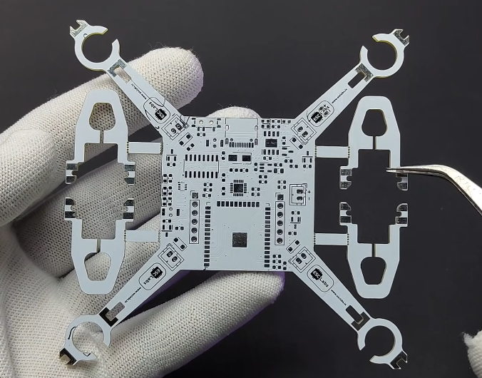
For drone companies aiming to shorten R&D cycles, enhance manufacturing consistency, and achieve scalable delivery, partnering with a PCBA provider—one equipped with capabilities in engineering review, precision SMT, quality inspection, and supply chain coordination—is a vital step in transitioning products from prototypes to mature, full-scale manufacturing. KingTop Technology aligns with specific project requirements to assist clients with manufacturing preparation, precision assembly, and quality control, supporting drone electronics through every stage from initial prototyping to mass production.
Through comprehensive design reviews, standardized production processes, tailored testing protocols, and continuous quality improvement, companies can establish a more reliable manufacturing system for flight control boards. This provides a robust hardware foundation for the ongoing development of drone products across industrial, commercial, and professional sectors. KingTop Technology emphasizes the synergy between manufacturing processes and quality management, helping clients boost production efficiency and ensure consistent delivery for their PCBA projects.
PCB assembly for drone flight control boards goes beyond the precise soldering of components; it is a critical process that integrates electronic design, manufacturing techniques, and quality management to create reliable products. By partnering with KingTop Technology, drone R&D teams and manufacturers can effectively advance their flight control board PCBA projects, building electronics manufacturing solutions tailored for the future of drone applications.