
Amidst the rapid development of industrial automation and intelligent manufacturing, the industrial robot controller board—serving as the robot’s “brain” and “nervous system”—demands exceptional motion precision, rapid response times, and system stability.
As a professional electronics manufacturing services (EMS) provider, KingTop Technology specializes in high-end industrial-grade PCB assembly and manufacturing.
Equipped with precision SMT placement machinery, rigorous quality control systems, and extensive experience in processing multi-layer and heavy-copper PCBs, we are dedicated to providing global clients with one-stop PCBA solutions for industrial robot controllers that offer high reliability and durability.
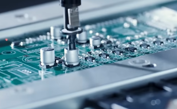
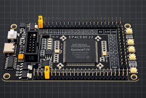
These controller boards typically integrate high-performance processing chips (such as FPGA, DSP, and ARM), multi-axis servo communication interfaces, industrial bus protocols (EtherCAT, CANopen, Profinet), safety circuits (STO), and complex power management modules.
The manufacturing and assembly (PCBA) of such PCBs fall into the category of high-end industrial production; they demand not only extreme placement precision but also adherence to strict industrial standards regarding quality control and testing/verification throughout the entire manufacturing process.
The following section provides a comprehensive breakdown of the complete process and critical milestones for industrial robot controller PCB assembly, covering technical specifications, the manufacturing workflow, and quality control.
I. Technical Characteristics and PCB Assembly Challenges of Industrial Robot Controller Boards
Manufacturing PCBA for industrial robot controllers differs significantly from standard consumer electronics assembly; the hardware architecture and operational environment present unique process challenges:
High-Density and Mixed-Package Assembly
Robot controller boards often require high-intensity computing power and multi-channel signal processing within a limited footprint. The boards feature a mix of components ranging from miniature surface-mount resistors and capacitors (such as 0201 or 01005 sizes) to high-pin-count, densely packed chips (BGA, QFN, CSP), as well as bulky power inductors, industrial-grade interface terminals, and heat sinks. The mixed assembly of high-density and irregularly shaped components places extremely high demands on solder paste printing and component placement accuracy.
High Heat Dissipation and Thick-Copper Multilayer Board Technology
The drive interface and power management sections of control boards often handle high currents; consequently, PCBs frequently utilize 4- to 12-layer high-Tg (Glass Transition Temperature) materials combined with thick-copper (≥2 oz) designs. Thick-copper boards possess high thermal mass, which can lead to uneven heat absorption and slow pad heating during reflow soldering—issues that easily trigger defects such as false soldering, cold joints, or “tombstoning.”
Extreme Requirements for Vibration and Environmental Interference Resistance
Robot control cabinets operating on factory floors must withstand continuous mechanical vibration, electromagnetic interference (EMI), high humidity, and dusty environments. This necessitates solder joints with exceptional mechanical and fatigue strength, alongside a rigorous conformal coating process following PCB assembly.
II. Comprehensive Analysis of the Industrial Robot Control Board PCB Assembly Process
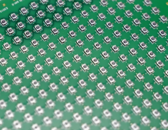
The PCB assembly process for industrial robot control boards encompasses key stages such as material pre-treatment, SMT (Surface Mount Technology) assembly, DIP (Dual In-line Package) insertion, testing, and protective coating.
Design for Manufacturability (DFM) Review and Production Preparation
Risk assessment and process validation prior to assembly.
DFM (Design for Manufacturability) Check
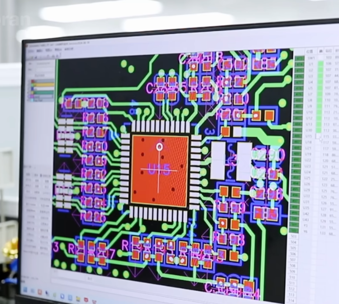
Evaluate the compatibility between pad designs and BGA/QFN pin pitches; inspect stencil aperture ratios.
Verify solder mask isolation between thermal vias and pads to prevent solder leakage during soldering.
Assess heat sink distribution on multilayer thick-copper boards and pre-configure preheating and reflow temperature profiles.
Precision Stencil Fabrication
Utilize laser cutting combined with electropolishing to produce nano-coated stencils, enhancing paste release performance for micro-pads (e.g., 0201 components or 0.4mm pitch BGAs). For stepped boards or areas with thick copper, “step stencils” (featuring localized thickness variations) are utilized to ensure a precise balance in solder deposition for components of varying sizes.
Material Pre-treatment and SMT Preparation
Environmental Control and Precise Solder Deposition
BGA Chip and PCB Baking
Industrial-grade BGAs and Moisture Sensitive Devices (MSDs) undergo baking in strict accordance with the J-STD-033 standard to remove moisture before production, thereby completely eliminating the “popcorn effect” during reflow soldering.
PCBs undergo stress relief and baking treatments prior to assembly to prevent warping or twisting of high-layer-count boards during high-temperature soldering.
Fully Automated Solder Paste Printing and SPI Inspection
Fully automated solder paste printers are used in conjunction with high-quality SAC307 or lead-free SAC305 solder paste, with real-time monitoring of the printing environment (temperature: 22–25°C; humidity: 40%–60%).
A 3D Solder Paste Inspection (SPI) system is employed for 100% inspection, automatically measuring solder paste volume, thickness, area, and offset to ensure that defective prints are intercepted and cleaned prior to component placement.
High-Precision Placement and Ten-Zone Reflow Soldering
Precise Component Positioning and Thermal Profile Control
High-Speed and High-Precision Placement
High-precision placement machines are used for component mounting. High-speed placement heads handle miniature components, while high-density BGAs, FPGAs, and industrial interface chips are positioned and placed using vision recognition systems, maintaining placement accuracy within ±0.03mm.
Ten-Zone Nitrogen Reflow Soldering
To accommodate differences in heat absorption between thick copper boards and high-density components, ten-zone (or twelve-zone) nitrogen reflow ovens are utilized. Introducing a nitrogen atmosphere (maintaining oxygen concentration below 500 ppm) effectively reduces oxidation reactions on pads and leads at high temperatures, significantly improving BGA solder joint wettability and reducing voiding rates.
Post-soldering Quality Inspection and DIP Assembly
Comprehensive defect screening and through-hole soldering.
3D AOI and 3D X-Ray Inspection
After SMT assembly, 3D AOI (Automated Optical Inspection) is used to detect defects such as misplaced components, missing components, reversed polarity, bridging, and tombstoning.
3D X-Ray inspection is employed for 100% sampling or full inspection of hidden solder joints (e.g., BGA, QFN), focusing on BGA voiding rates (voiding must be controlled within 15%, with industrial standards typically requiring less than 10%).
DIP Through-hole Assembly and Selective Wave Soldering
Components such as high-power relays, terminal blocks, and electrolytic capacitors on the robot control board are assembled using the DIP (Dual In-line Package) through-hole method.
Selective soldering replaces traditional wave soldering; solder and flux are applied only to the specific leads requiring connection. This ensures optimal solder penetration and fill while preventing thermal shock damage to SMT components already mounted on the board.
Functional Testing (FCT) and Conformal Coating
Final performance and protection inspection before shipment.
PCBA Cleaning and Cleanliness Testing
Fully automated aqueous cleaning machines are used to deeply clean the soldered control boards, thoroughly removing flux residues to prevent micro-short circuits or corrosion caused by ion migration during long-term operation.
Selective Conformal Coating
Industrial-grade conformal coating is applied to critical areas (avoiding terminal blocks, connectors, and test points) using an automated coating machine, followed by rapid curing in a UV (Ultraviolet) curing oven. This provides the control board with protection against moisture, salt spray, mold, and static electricity.
Functional Testing (FCT) and Burn-in Testing
The PCBA is mounted onto a dedicated test fixture and powered up to simulate the actual operating conditions of the robot controller. Key tests focus on multi-axis PWM output, servo communication interfaces, CAN/EtherCAT transceiver functionality, sensor inputs, and safety circuit operations.
High-temperature burn-in (e.g., continuous operation under power for 24–48 hours in a 60°C environment) is employed to screen out components prone to early-life failure, ensuring exceptional stability for the finished PCBA.
III. Core Elements of Quality Control for Industrial Robot Control Board PCBAs
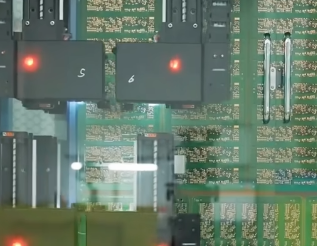
To ensure the industrial robot control board operates reliably for years without failure under harsh conditions, a robust quality management system must be established throughout the manufacturing process:
| Quality Control Dimension | Core Standards & Control Methods | Industrial-Grade Criteria |
| Workmanship Standard | IPC-A-610 Class 3 (Highest Standard for Electronic Assemblies) | Solder joint shape, wetting height, and clearance must strictly adhere to Class 3 requirements |
| BGA Void Rate | 3D X-Ray Inspection & Analysis | Single solder ball void rate < 10%, overall void rate < 15% |
| Solder Vertical Fill / Penetration (DIP) | Selective Wave Soldering Through-hole Penetration Monitoring | Through-hole solder fill rate reaches 75% or higher (100% recommended for Class 3) |
| Insulation & Protection | Ionic Contamination Testing & Conformal Coating Thickness Inspection | Coating thickness maintained at 30-75 μm, ionic residue< 1.56 μg/cm² |
Summary
The PCBA manufacturing process for industrial robot control boards is a systems engineering endeavor that integrates precision mechanics, materials science, and automated testing.
Producing highly reliable and durable industrial-grade robot controller hardware requires a combination of rigorous DFM analysis, precise stencil aperture design, nitrogen-purged reflow soldering, comprehensive AOI and X-ray inspections, and meticulous conformal coating and burn-in testing.
As a provider of high-end industrial electronics manufacturing services, KingTop Technology consistently adheres to a strict quality management system. Leveraging high-precision placement equipment and extensive experience in industrial board manufacturing, the company offers global clients a one-stop PCBA manufacturing solution for industrial robot control boards—spanning everything from engineering optimization and SMT assembly to full-function testing.