In modern industrial automation, humanoid robotics, collaborative robotic arms, and high-end CNC equipment, the robotic servo drive is regarded as the “muscle control center” of the entire system.
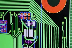
Serving as the power and control core that translates control commands into precise torque, speed, and position, the servo drive PCB incorporates a highly complex circuit architecture.
It integrates high-speed digital signal processing chips (DSP, MCU, FPGA), high-precision analog sampling circuits, and communication interfaces (such as EtherCAT and CANopen), while also densely housing high-power switching components (such as MOSFETs, IGBTs, and SiC modules) and large-capacity electrolytic capacitors for energy storage.
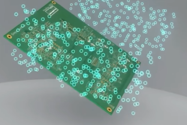
As robotics evolve toward higher dynamic response, greater power density, lighter weight, and enhanced reliability, the precision assembly (PCBA) of servo drive boards faces unprecedented manufacturing challenges.
The widespread use of miniaturized components, the need for thermal management of high-power devices, the suppression of electromagnetic interference (EMI) caused by high-frequency switching, and the requirement for long-term reliability in harsh industrial environments all place rigorous demands on modern Electronics Manufacturing Services (EMS) and precision assembly processes.
This article provides a systematic, in-depth exploration of the core processes, key technologies, quality control measures, and future trends regarding the precision assembly of robotic servo drive boards.
I. Electrical Architecture and Component Characteristics of Robotic Servo Drive Boards
Achieving high-precision assembly requires a profound understanding of the servo drive board’s unique electrical architecture and component characteristics. Fundamentally, a servo drive board is a hybrid system integrating “low-voltage control” and “high-voltage/high-current drive” functions; its board design and component layout are characterized by a mix of high and low voltages, significant heat generation, and high sensitivity.
Power Components and Thermal Management Structures
The core function of a servo drive board is to drive motor operation, a task that requires outputting high currents through an inverter bridge.
Semiconductor Power Devices: Surface-mount or through-hole MOSFETs, IGBT modules, and even advanced Silicon Carbide (SiC) MOSFETs are widely used. These devices generate significant dynamic and conduction losses during high-speed switching operations.
Thermal Design and Assembly: To ensure efficient heat dissipation, many power devices utilize packages featuring bottom thermal pads (e.g., TO-263, DirectFET, or specialized power module packages) or require close contact with metal-core PCBs (MCPCBs) or aluminum heat sinks. During assembly, factors such as solder paste fill at the thermal pad and the control of bottom-side voiding directly determine the efficiency of heat transfer; even minor soldering defects can lead to localized overheating and trigger thermal breakdown.
Mixed High-Speed Digital and Precision Analog Circuits
The control section of the driver board houses high-performance microcontrollers (MCUs) or digital signal processors (DSPs) that operate at very high frequencies and feature signals with steep edges.
High-Speed Signal Integrity: These boards typically employ multi-layer architectures (e.g., 6, 8, or more layers, including HDI boards) with extremely high routing density. Impedance matching and crosstalk control are critical.
Miniaturized Passive Components: Extensive use is made of chip resistors and capacitors in 0201 or even 01005 sizes, alongside fine-pitch IC packages (such as QFN, BGA, and LQFP). This necessitates micron-level placement accuracy to prevent micro-shorts or cold solder joints.
II. Preparation and Process Planning for Precision PCB Assembly
High-quality precision assembly relies on far more than just the soldering equipment on the shop floor; rigorous process planning, materials management, and preliminary DFM (Design for Manufacturability) reviews form the cornerstone of success.
Substrate Selection and Impedance Control
Robot servo driver boards operate over long periods in environments characterized by vibration, high electromagnetic interference (EMI), and alternating thermal stress.
Board Material Characteristics: High-Tg (glass transition temperature, e.g., >170°C) FR-4 copper-clad laminates are typically selected, or high-thermal-conductivity copper-base PCBs are used in power zones to prevent deformation or delamination under high-temperature and high-power load conditions.
Surface Finish: ENIG (Electroless Nickel Immersion Gold) or OSP (Organic Solderability Preservative) processes are recommended. ENIG offers excellent surface flatness—ideal for soldering fine-pitch QFN and BGA components—as well as low contact resistance and strong oxidation resistance.
Component Storage and Moisture Sensitivity Level (MSL) Management
Many integrated circuits and power modules on servo drive boards are highly sensitive to moisture.
Baking and Moisture Protection: Strict adherence to the IPC/JEDEC J-STD-033 standard is required, involving precise temperature and humidity control and baking for components with an MSL of Level 3 or higher. If moisture-laden components are subjected to the high temperatures of reflow soldering, rapid vaporization can cause “micro-explosions,” leading to internal wire bond breakage or package cracking.
Stencil Design and Solder Paste Selection
The stencil is a critical tool determining the quality of solder paste printing.
Step Stencil Technology: Servo drive boards feature a mix of tiny 0201-sized passive components and large power modules, creating orders-of-magnitude differences in solder paste volume requirements. A laser-cut, electropolished step stencil must be used to locally adjust thickness (increasing or decreasing it); this ensures sufficient solder volume for large components—supporting structural integrity and heat dissipation—while preventing bridging (short circuits) on fine-pitch pins.
Solder Paste Selection: High-quality, lead-free, no-clean solder paste (such as SAC305 alloy) of Type 4 or Type 5 is typically used. These pastes feature fine powder particles and stable viscosity, making them perfectly suited for fine-pitch printing applications.
III. Core Surface Mount Technology (SMT) and High-Precision Manufacturing
Upon entering the SMT workshop, the manufacturing process undergoes rigorous control to ensure that every component is precisely and securely mounted at its designated location on the PCB.
3D Solder Paste Inspection (SPI)
The printing stage is critical to ensuring SMT quality at the source.
In-line SPI Application: High-precision 3D SPI systems are deployed after the printer. They utilize optical 3D projection technology to inspect solder paste thickness, area, volume, and positional offset in real-time.
Closed-loop Control: If the SPI system detects trends such as insufficient solder or solder bridging in a batch, it automatically triggers an alarm and communicates with the printer to adjust squeegee pressure or alignment compensation, thereby eliminating defects before the component placement stage.
High-Precision Multi-functional Placement and Odd-form Component Assembly
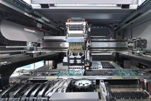
Servo drive boards feature a wide variety of components, ranging from high-volume chip resistors and capacitors handled by high-speed “shooter” machines to complex ICs and odd-form power components handled by high-precision multi-functional placement machines.
Vision Recognition and Alignment: Advanced machine vision algorithms are employed to perform multi-point alignment on BGA solder ball arrays and QFN edge electrodes, compensating for minute deformations caused by thermal expansion and contraction.
Pressure Control: For precision ICs and connectors featuring spring contacts or special housings, the placement head must possess programmable, precise downward pressure control capabilities to prevent cracking chips or damaging pins.
IV. Reflow Soldering and Thermal Profile Optimization
Reflow soldering is the stage of PCB assembly involving the most intense chemical and physical changes; it directly determines the microstructure and mechanical strength of the solder joints.
Temperature Zone Settings and Thermal Profile Testing
Robot servo drive boards exhibit significant variations in thermal capacity due to uneven copper foil thickness (e.g., thin copper foil in control zones versus thick copper foil and large copper pour areas in power zones).
Thermal Balance Challenge: If temperature zones are improperly set, thin or lightweight areas may overheat and scorch, while thick-copper power zones might fail to reach the necessary melting point, resulting in cold or weak solder joints.
Multi-point Temperature Verification: During pilot production, infrared or thermocouple data loggers must be used. Test points should be placed in PCB areas with varying thermal masses (e.g., BGA centers, high-power IGBT pins, and edge grounding copper planes) to meticulously calibrate the temperatures of the reflow oven’s zones and the conveyor belt speed.
Nitrogen Protection and Voiding Control
The soldering quality of power devices is critical to the lifespan of servo drive boards.
Nitrogen (N2) Reflow Soldering: Injecting high-purity nitrogen into the reflow zone lowers oxygen levels, significantly enhancing solder paste wettability and reducing surface oxidation, resulting in brighter, fuller solder joints.
Solder Pad Void Suppression: Thermal pads beneath high-power MOSFETs and power modules are highly prone to bubble (void) formation. Voids directly impede heat conduction, leading to localized overheating. By optimizing stencil aperture designs (such as using “tic-tac-toe” or distributed grid patterns) and fine-tuning peak reflow temperatures and soak times, the void ratio can be strictly controlled to meet IPC standards (typically requiring less than 15% or even 10%).
V. Advanced Packaging Protection: Underfill and Conformal Coating Processes
Robots operate in complex environments often characterized by mechanical vibration, shock, and harsh conditions such as oil contamination, dust, and humidity; consequently, soldering alone is insufficient to ensure long-term reliability.
Underfill Process
For core control chips, BGAs, and leadless high-power packages, vibration can easily cause solder joints to fracture due to stress concentration.
Capillary Flow and Curing: Low-viscosity, high-flowability epoxy underfill is dispensed at the component edges. Capillary action draws the material rapidly beneath the component, encapsulating and securing all solder joints. Subsequent medium-temperature curing forms a uniform stress-dispersing layer, significantly enhancing resistance to drops and mechanical vibrations.
Conformal Coating Selection and Application
The internal circuitry of the robot drive board features a mix of high- and low-voltage components, making it highly susceptible to arcing, tracking, or short circuits in high-humidity or dusty environments.
Precision Spraying: A selective coating machine is used to apply a uniform layer of polyurethane or silicone conformal coating—typically 30–50 microns thick—onto the PCB surface, while precisely avoiding areas such as connector sockets and heatsink contact surfaces.
Protective Performance: This protective film effectively isolates the board from moisture, salt spray, and conductive dust, ensuring highly reliable operation of the drive board in industrial settings.
VI. Quality Inspection, X-ray Imaging, and Reliability Verification
The final line of defense in precision assembly is a rigorous, comprehensive inspection system designed to ensure that every servo drive board leaving the factory is defect-free.
Automated Optical Inspection (AOI) and 3D AXI
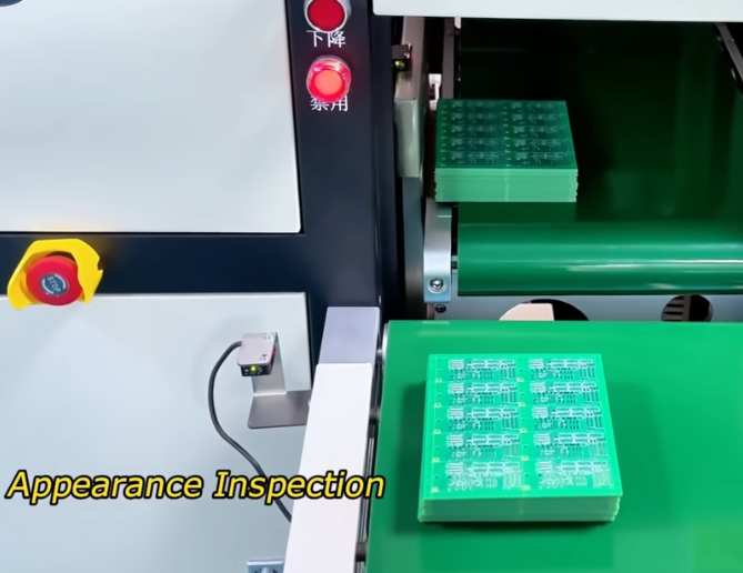
Surface Defect AOI: Multi-angle optical cameras scan for issues such as missing or incorrect components, reversed polarity, misalignment, and surface solder joint defects.
X-ray Non-Destructive Inspection (AXI): Since many power components and QFN-packaged solder joints on the servo drive board are completely obscured, traditional AOI cannot inspect their internal state. High-resolution 3D AXI equipment is required to penetrate the packaging and perform 3D tomographic scanning to analyze the internal morphology, wetting characteristics, and void ratios of hidden solder joints.
Functional Circuit Testing (FCT) and Burn-in Testing
Functional Testing (FCT): A high-precision analog test bench is set up to input standard control commands to the drive board and apply actual or simulated motor loads. This process verifies parameters such as PWM output waveforms, current sensing accuracy, encoder feedback interface performance, communication bus response speed, and the trigger sensitivity of protection circuits (overcurrent, overvoltage, and over-temperature protection).
Burn-in Testing: The assembled drive boards undergo dynamic burn-in for tens of hours in a high-temperature, high-load chamber. This process filters out components prone to early-stage failure, ensuring that the drive boards delivered for integration into the robot units possess exceptional industrial-grade stability.
VII. Conclusion
The precision PCB assembly of robot servo drive boards is a cutting-edge manufacturing technology that integrates microelectronics, thermodynamics, materials science, and automated control. As an industry-leading provider of electronics manufacturing and high-precision assembly services, KingTop Technology is dedicated to delivering exceptional manufacturing solutions for servo drives and high-reliability smart hardware to global customers.
From the design and component selection for high-density multilayer boards to high-precision 3D SPI (Solder Paste Inspection) control; from optimizing reflow temperature profiles for complex thermal mass scenarios to strictly controlling void rates in power devices and applying conformal coatings—KingTop Technology pursues excellence in every process step. These efforts directly determine the motion precision and operational lifespan of the robots.
Driven by the explosive growth of humanoid robotics and high-end industrial automation, servo drive boards are rapidly evolving toward higher power density, miniaturization, and full digitalization.
Looking ahead, and leveraging KingTop Technology’s deep expertise in smart manufacturing production lines, the precision assembly technology for robot servo drive boards is poised to reach new heights of automation, intelligence, and micro/nano-manufacturing. This progress will be fueled by the widespread adoption of third-generation semiconductors (such as SiC and GaN), embedded passive component technology, and the deep integration of AI-based machine vision, thereby providing a steady supply of highly reliable power cores for the global intelligent equipment industry.