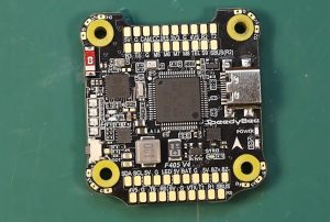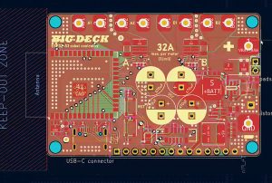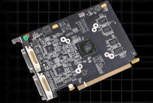

Industrial drones are evolving beyond traditional aerial photography equipment, expanding into specialized fields such as industrial inspection, energy infrastructure maintenance, emergency rescue, precision surveying and mapping, agricultural crop protection, and environmental monitoring in complex settings.
Compared to consumer-grade drones, industrial-grade drones require not only stable flight control capabilities but also the ability to operate reliably under challenging conditions—including continuous vibration, temperature fluctuations, hot and humid environments, electromagnetic interference, dust ingress, and extended operational durations.
These requirements ultimately hinge on a critical hardware foundation: rugged industrial drone PCB assembly.
“Rugged” in this context does not simply mean using thicker circuit boards, extra solder, or a sturdier enclosure. Rather, it entails building an electronic hardware system capable of withstanding real-world industrial operating conditions through careful PCB material selection, power and signal integrity design, component packaging, soldering processes, mechanical integration, environmental protection, and rigorous reliability validation.
For industrial drone manufacturers, flight control R&D teams, and Electronics Manufacturing Services (EMS) providers, the primary concern is not merely whether a circuit board can power on, but whether it can deliver consistent, predictable, and verifiable performance over missions lasting hundreds of hours or longer.
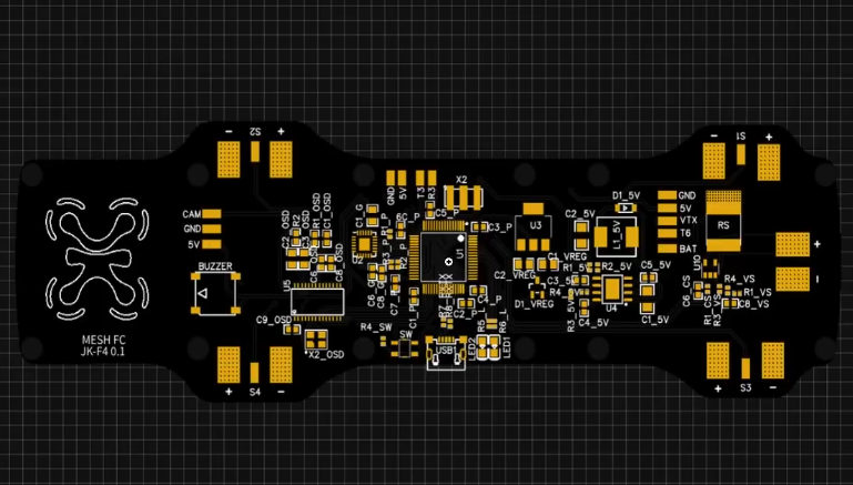
I. What is Rugged Industrial Drone PCB Assembly?
Rugged industrial drone PCB assembly refers to the targeted design, component assembly, soldering, testing, and reliability validation of printed circuit boards (PCBs), tailored to the specific operating environments, mission payloads, and service life requirements of industrial drones.
This encompasses not only flight control boards but also power management boards, motor drive boards, navigation and positioning boards, communication modules, mission payload interface boards, and battery management systems (BMS).
1.1 Why Do Industrial Drones Require Higher-Grade PCB Assembly?
While standard electronic devices typically operate under relatively stable conditions—in terms of temperature, humidity, and mechanical stress—industrial drones must contend with far more complex operational environments.
Mechanical Vibration and Shock: Fluctuations in motor speed, propeller imbalance, airframe resonance, and the impact of landing all exert persistent stress on solder joints, connectors, and the overall PCB structure.
Wide-Temperature Operation: Exposure to extreme cold at high altitudes, high temperatures on the ground during summer, and heat accumulation within enclosed compartments can alter component parameters and affect the fatigue characteristics of solder joints.
Power Transients: Motor startup, acceleration, and braking can trigger voltage fluctuations, ground bounce, and electromagnetic interference (EMI), potentially disrupting flight control systems, GNSS, and communication links.
Moisture and Contamination: Condensation, salt spray, dust, pesticide droplets, and industrial pollutants can lead to corrosion, electrical leakage, or a degradation in insulation performance.
Long-Term Mission Reliability: Industrial tasks—such as infrastructure inspection, surveying, and automated operations—often require repeated, sustained flights; therefore, short-term functional testing in a laboratory setting is insufficient.
Consequently, the primary objective of ruggedized PCB assembly is to mitigate the performance drift, intermittent faults, and long-term failures caused by environmental stress on electronic systems.
1.2 “Rugged” Does Not Simply Mean Adding More Protection
In engineering practice, a rugged design must be tailored to the specific operational environment.
For instance, agricultural drones may prioritize moisture resistance, protection against chemical contamination, and the reliability of high-power electrical systems.
Drones used for power-line inspection might focus more on electromagnetic compatibility (EMC), navigation stability, and resistance to long-term vibration. Meanwhile, drones deployed for maritime inspection require specialized measures against salt-spray corrosion, high humidity, and heat, as well as robust connector protection.
Indiscriminately increasing the protection level for every component—without considering the actual application—can lead to unnecessary costs, thermal management challenges, complex maintenance, and increased weight.
True industrial-grade reliability lies in strategically allocating limited resources—weight, space, power budget, and cost—to the critical components most prone to failure or those most vital to mission safety.
II. System Architecture of Industrial Drone PCBs: Distinct Reliability Challenges for Different Circuit Boards
Ruggedized PCB assembly cannot rely on a “one-size-fits-all” technical solution. Circuit boards within industrial drones serve distinct functions, characterized by significant variations in current levels, signal frequencies, thermal loads, mechanical stresses, and the consequences of potential failure.
2.1 Flight Controller PCB
Core requirements: Low noise, low latency, and high stability.
The flight controller typically integrates an MCU or processor, an Inertial Measurement Unit (IMU), a barometer, memory, and communication interfaces. Design priorities include ensuring the quality of sensor data, clock stability, power supply integrity, and the deterministic nature of control signals. Factors such as IMU placement, soldering quality, and mechanical stress on the board can all affect attitude estimation.
2.2 Power Distribution and Management PCB
Core requirements: Current-carrying capacity, thermal stability, and transient response.
These boards handle battery input, voltage conversion, load distribution, and system protection. Design considerations include copper cross-sectional area, connector current ratings, MOSFET conduction losses, switching power supply layout, and transient voltages. For high-current paths, simply increasing copper thickness is insufficient; one must also evaluate vias, current crowding, thermal dissipation, and contact resistance.
2.3 Electronic Speed Controller (ESC) PCB
Core requirements: High current, high switching frequency, and low parasitic parameters.
ESCs require rapid switching of power semiconductors to control brushless motors. Parasitic inductance in the power loop, gate drive layout, placement of DC-bus capacitors, and thermal management structures all influence switching overshoot, power loss, and electromagnetic radiation. During assembly, critical focus must be placed on the soldering of power components, voids in thermal pads, component alignment, and the integrity of high-current connection points.
2.4 Navigation and Communication PCB
Core requirements: RF integrity, low noise, and impedance control.
Modules for GNSS, telemetry, data transmission, and other wireless communications are highly sensitive to RF trace routing, ground plane continuity, antenna interfaces, and power supply noise. Interference generated by high-power electronic speed controllers (ESCs) can reduce receiver sensitivity. Therefore, system-level design—encompassing layout isolation, return paths, filtering networks, and wiring harness routing—is essential.
2.5 System-Level Synergy Outweighs Individual Board Specifications
Passing tests at the flight controller board level does not guarantee equivalent reliability for the entire aircraft. Industrial drones typically comprise multiple electronic modules, wiring harnesses, connectors, structural components, and thermal management parts; system-level failures frequently occur at the interfaces between these elements.
For instance, while both a flight controller board and a power distribution board may meet their respective design specifications, excessive ground impedance between them can still cause sensor measurements to be corrupted by switching noise. Alternatively, a PCB might pass vibration testing, yet a lack of strain relief on the wiring harnesses could lead to intermittent connector disconnections.
Consequently, the assembly of robust PCBs must account for both individual board quality and system integration quality; electronic assembly and overall system engineering should not be treated as separate, disconnected processes.
III. PCB Substrate and Stack-up Design: The Physical Foundation of Reliability
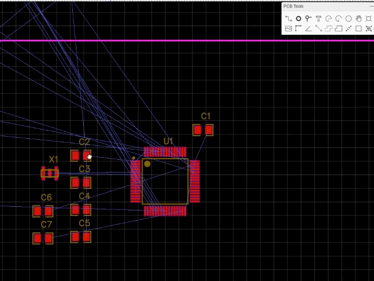
Selecting materials for industrial drone PCBs requires a balanced consideration of thermal, mechanical, and electrical properties, as well as manufacturability and cost. Material parameters must be aligned with actual operating conditions, rather than simply pursuing the highest possible values for any single metric.
3.1 Choosing Between FR-4, High-Tg, and High-Performance Substrates
FR-4 is a common glass-fiber-reinforced epoxy copper-clad laminate. For most industrial drone control boards and standard digital circuit boards, a suitably specified FR-4 remains a viable solution.
For designs subject to higher thermal loads, frequent thermal cycling, or more stringent dimensional stability requirements, high-Tg (glass transition temperature) materials should be evaluated. It is important to note that Tg does not equate to the maximum allowable continuous operating temperature of a PCB, nor does it serve as a standalone indicator of the board’s overall heat resistance.
When selecting materials, one should also consider:
CTE (Coefficient of Thermal Expansion): Specifically, the Z-axis thermal expansion behavior, which influences the stress exerted on the copper plating within through-holes during thermal cycling.
Td (Decomposition Temperature): This reflects the temperature at which the material begins to thermally decompose; however, it should not be used directly as a metric for long-term operating temperature.
Dielectric Constant and Loss Factor: These influence propagation delay, signal loss, and impedance control in high-speed digital signals and RF links.
Moisture Absorption and Insulation Properties: Material performance in humid environments affects leakage currents, the risk of corrosion, and the stability of high-impedance circuits.
A high glass transition temperature (Tg) does not imply that every project requires the same high-end substrate material. The choice should be based on factors such as the soldering temperature profile, board thickness, layer count, copper distribution, and operating temperature.
3.2 Multilayer Board Design: Balancing Size, Routing, and Reliability
Industrial drones require the integration of controllers, sensors, power supplies, and communication circuits within a limited onboard space. Multilayer PCBs help shorten critical signal paths and provide a more controlled structure for power distribution and grounding.
However, increasing the number of layers introduces challenges related to manufacturing costs, stack-up tolerances, interlayer alignment, and thermal stress management.
A more sound design approach involves planning signal layers, ground planes, and power planes based on specific requirements, while ensuring that high-speed signals have a continuous reference plane.
For critical high-speed signals, impedance control should be determined in conjunction with the actual stack-up, dielectric thickness, copper thickness, and manufacturing tolerances—rather than simply entering a target impedance value into routing software.
3.3 Copper Thickness, Vias, and High-Current Paths
Power distribution boards and electronic speed controller (ESC) boards often need to handle significant current loads. Increasing copper thickness can reduce conductor resistance, but it also impacts fine-line etching, trace-width control, thermal balance during soldering, and manufacturing costs.
Engineering design requires a comprehensive evaluation of:
The effective cross-sectional area of conductors and the resulting temperature rise;
The number of vias, hole diameters, barrel copper thickness, and current distribution;
Local current density between pads and connectors;
Thermal coupling from high-current components and the heat-dissipation capacity of copper planes;
The physical separation between high-current paths and sensitive analog circuits.
It is particularly important to note that the current-carrying capacity of a PCB trace cannot be determined solely by its nominal copper thickness. The actual temperature rise also depends on the width of the copper foil, its position (inner or outer layer), ambient temperature, airflow conditions, and the overall thermal management structure.
For high-current systems, designs should be verified through calculations, thermal simulations, and prototype measurements, rather than adopting a fixed copper thickness as a universal standard for all industrial drones.
IV. Component Selection and PCB Assembly: Preventing Weak Links from Becoming Sources of System Failure
When selecting components for rugged industrial drones, one must look beyond package dimensions, procurement costs, and nominal specifications. It is far more critical to evaluate whether a component can withstand actual operating temperatures, vibrations, voltage fluctuations, and mission duty cycles, and whether it can be reliably assembled using the intended manufacturing process.
4.1 Component Grade Must Match Actual Operating Conditions
Components commonly used in industrial drones—such as MCUs, IMUs, power MOSFETs, power management ICs, connectors, and memory modules—should be selected based on manufacturer datasheets, reliability data, and relevant certifications.
Particular attention must be paid to operating temperature ranges, voltage ratings, current derating, package thermal resistance, vibration tolerance, and product lifecycle status.
It is important to note that even if an individual component has a wide operating temperature range, this does not automatically confer the same level of environmental adaptability upon the entire PCB assembly.
For critical components, one must also evaluate supply chain stability, batch-to-batch consistency, traceability, and the requirements for validating alternative parts. Unverified substitutes can alter electrical parameters, thermal characteristics, soldering process windows, or mechanical reliability.
4.2 SMT Assembly Quality and Solder Joint Reliability
Surface Mount Technology (SMT) is a primary method for assembling PCBs in modern industrial drones. For components such as flight control processors, IMUs, memory modules, and power management ICs, issues like placement misalignment, solder paste printing defects, insufficient solder joint wetting, or improper reflow temperatures can all become root causes for future failures.
A reliable SMT process requires the establishment of a validated process window, based on component package specifications, PCB thermal capacity, solder paste characteristics, and manufacturer recommendations.
Special care is required for BGA and QFN packages, as well as power components with large thermal pads, to ensure proper solder joint formation and to minimize internal voids. For packages featuring thermal pads, factors such as solder paste coverage, stencil aperture design, stencil thickness, and reflow conditions collectively influence the void ratio and the component’s thermal conductivity. However, the requirement cannot be summarized simply by saying “the lower the void ratio, the better.” Specific acceptance criteria should be determined based on component data, applicable IPC standards, product risk, and customer specifications.
4.3 Connectors, Solder Pads, and Mechanical Stress Relief
In industrial drones, connectors often prove to be weaker links than one might expect. Battery power interfaces, motor phase wires, sensor harnesses, and onboard communication interfaces are frequently subjected to insertion/extraction forces, cable tension, and airframe vibration.
Design considerations should focus on the mechanical anchoring of connectors, pad design, locking mechanisms, current ratings, and environmental protection.
For heavier connectors or large components, it may be necessary to implement mechanical support, structural bracing, or stress-relief measures to reduce the load borne by solder joints.
In particular, the weight of unsupported cable harnesses should never be allowed to exert long-term stress on PCB solder pads. Even if electrical continuity is initially sound, persistent flexing and vibration can gradually lead to solder joint cracking, copper foil delamination, or poor electrical contact.
V. Vibration and Shock Resistance: An Often Underestimated Engineering Challenge for Industrial Drone PCBs
The mechanical reliability of an industrial drone is a systemic characteristic. There is a complex coupling between motors, propellers, the airframe, vibration-damping structures, PCB mounting points, and cable harnesses; localized structural issues can be significantly amplified at specific rotational speeds or flight attitudes.
5.1 Identifying Resonance: Why Simply Adding More Screws Isn’t the Answer
A PCB’s natural frequency is influenced by factors such as board thickness, dimensions, the location of mounting points, the mass of components, and the method of support. When the frequency of an external excitation approaches the structure’s natural frequency, the vibration response can be dramatically amplified.
Consequently, the placement of mounting holes for flight control boards, the height of standoffs, the durometer (stiffness) of vibration-damping pads, and the layout of components must all be evaluated in the context of the entire airframe structure.
While adding more mounting points can increase rigidity, it may also shift the resonant frequency or transmit greater mechanical stress to the circuit board.
Similarly, softer vibration-damping materials are not always better; supports that are too soft can lead to excessive movement, which may compromise sensor readings or the stability of connectors. A more rational approach involves first identifying the primary sources of excitation and the relevant vibration frequency bands, then optimizing the mounting scheme by integrating structural analysis, experimental measurements, and actual flight data.
5.2 IMU Sensitivity to the PCB Mechanical Environment
An IMU measures a drone’s motion state via accelerometers and gyroscopes. Its output data is influenced not only by the device’s inherent performance but also by its mounting location, board-level stress, temperature fluctuations, and mechanical vibrations.
For a flight control PCB, the following aspects should be carefully evaluated:
Whether there is significant localized board bending or components that generate high thermal loads in the vicinity of the IMU;
Whether there is any undesirable coupling between power switches, high-power components, and the sensors;
Whether the PCB mounting method introduces unstable mechanical stress;
Whether the sensor calibration, filtering, and structural vibration-damping measures form a coherent and effective strategy.
Simply placing the IMU at the geometric center of the circuit board does not guarantee an optimal position. The final placement must be validated by considering the vibration modes of the entire airframe, airflow patterns, the distribution of heat sources, and the specific requirements of the flight control algorithms.
5.3 Solder Joint Fatigue and the Securing of Large Components
Prolonged vibration and thermal cycling can lead to fatigue damage in solder joints—a risk particularly prevalent around heavy components, connectors, power modules, and areas near the edges of the PCB.
For components that require additional support, design evaluations may justify the use of mechanical fasteners, appropriate structural adhesives, or localized mechanical bracing.
It must be noted, however, that such reinforcement materials can alter local stiffness and heat transfer characteristics, and may complicate rework; they are not a substitute for sound pad design and proper soldering processes.
Similarly, conformal coatings should not be viewed as a universal solution for mechanical reinforcement. Their suitability must be determined based on the specific material’s elasticity, adhesion, curing conditions, and long-term performance in the operating environment.
VI. Thermal Management and Power Integrity: High Reliability Requires More Than Just Heat Sinks
Industrial drones often have limited internal space, with electronic equipment frequently housed in enclosed or semi-enclosed compartments. Heat generated by high-power components can accumulate in specific areas of the PCB, negatively impacting processor performance, sensor accuracy, the lifespan of capacitors, and the integrity of solder joints. 6.1 Establishing a Complete Thermal Path from Chip to External Environment
Thermal management should not be limited to the size of a heatsink; rather, it requires an analysis of the entire heat transfer path, including the chip junction, package, solder joints, copper layers, PCB, thermal interface materials, and the enclosure structure.
For electronic speed controllers (ESCs) and power management boards, focus should be placed on MOSFET conduction and switching losses, losses in magnetic components, and overall power conversion efficiency. For flight control boards, it is essential to ensure that high-temperature power components do not cause significant thermal drift in the IMU, voltage references, or other sensitive elements.
While thermal simulation can help identify “hot spots,” models must ultimately be validated through representative load testing and temperature measurements. Such testing should, as closely as possible, replicate actual operating conditions—including enclosure temperature, airflow, mounting configuration, and duty cycles.
6.2 Interactions Between Power Transients and Sensitive Signals
The power system of a drone is not a perfectly stable DC source. Motor acceleration, braking, and load switching can trigger transient currents, leading to voltage dips, spikes, and ground potential differences.
If the power supply for the flight controller or sensors is affected by these disturbances, it may result in communication errors, increased measurement noise, processor resets, or instability in the control system.
Key engineering considerations include:
Input and output decoupling networks for power converters;
The area of high-current loops and their respective return paths;
The proper organization of analog, digital, and power grounds;
The stability of power rails under dynamic loads;
Under-voltage protection, over-current protection, and power-up sequencing for critical power rails.
It should be noted that analog and digital grounds do not necessarily need to be physically separated into distinct copper planes. In many high-speed mixed-signal designs, a continuous, low-impedance reference plane—paired with well-planned current return paths—is often more effective. The specific grounding strategy should be determined based on the circuit architecture and electromagnetic compatibility (EMC) objectives.
6.3 EMI and EMC: Preventing Interference with Flight Control Systems
Electromagnetic Interference (EMI) and Electromagnetic Compatibility (EMC) are critical design considerations for industrial drones. Electronic speed controller (ESC) switching nodes, DC-DC converters, high-speed processor interfaces, RF transmission modules, and wiring harnesses can all serve as sources of interference or coupling paths.
Effective control measures include the strategic placement of high-noise and sensitive circuits, the minimization of high-frequency switching loops, the optimization of filter layouts, the assurance of continuous reference planes, and the implementation of proper shielding or routing isolation for critical wiring harnesses.
For GNSS, magnetometers, and telemetry communication modules, particular attention must be paid to the impact of high-power supply systems and radio transmission systems on reception performance. Simply adding filter capacitors to a PCB is insufficient to resolve all system-level interference issues.
EMC design should be integrated across the schematic, PCB layout, wiring harness planning, and overall mechanical structure phases. Furthermore, the risk of requiring late-stage modifications can be mitigated through appropriate pre-compliance testing and formal verification.
VII. Moisture Protection, Corrosion Resistance, and Conformal Coating: Establishing Protection Strategies Based on Operational Environments
Not all industrial drones require the same level of protection. For inspection equipment operating in dry, indoor environments, basic protection may suffice; however, drones deployed in agricultural, coastal, maritime, or high-humidity environments require more rigorous contamination control and assessments of material compatibility.
7.1 The Role and Limitations of Conformal Coating
Conformal coating is typically applied to enhance a PCB’s resistance to moisture, certain contaminants, and specific environmental factors. Common types include acrylic, polyurethane, silicone, and other specialized coating materials.
These materials vary in terms of flexibility, temperature resistance, chemical tolerance, curing methods, reworkability, and long-term stability; the choice should be based on the specific application environment and manufacturing processes.
Before application, it is essential to manage surface contamination, flux residues, and moisture levels on the board. For high-impedance circuits, fine-pitch pads, and sensitive sensors, residual contaminants can lead to electrical leakage or electrochemical migration; therefore, the cleaning process and the coating material must be validated in tandem.
7.2 Areas Requiring Special Attention
The following areas often require careful evaluation:
Fine-pitch components, connector pins, and zones prone to the accumulation of contaminants;
High-impedance analog inputs, voltage sampling points, and sensor interfaces;
Areas susceptible to condensation, salt exposure, or chemical mists/droplets;
Battery interfaces and external wiring harness connections;
Areas requiring thermal contact, optical inspection, or future maintenance/repair.
Improper application can introduce new issues—such as covering test points, contaminating connector contacts, impeding heat dissipation, or leaving residual volatile substances due to incomplete curing. Consequently, it is necessary to clearly define the areas to be coated, masking requirements, target coating thickness, and inspection methods.
7.3 Conformal Coating Does Not Equal Full-Device Waterproofing
The presence of a conformal coating on a PCB does not mean the entire device is capable of withstanding immersion, continuous water spraying, or high-pressure washing. The protection of an entire device also depends on its enclosure, seals, ventilation structures, connectors, cable entries, and pressure-variation management. For products with specific dustproof and waterproof rating requirements, full-device verification must be conducted in accordance with the target ratings and applicable standards; one cannot rely solely on PCB coatings to guarantee such performance.
In maritime environments, it is also necessary to evaluate salt-spray corrosion, galvanic corrosion (caused by the contact of dissimilar metals), and the material compatibility of connectors. In agricultural environments, one must verify that any cleaning agents, fertilizers, or pesticides that the device might come into contact with are compatible with the materials used for protection.
VIII. Quality Testing and Reliability Verification: Moving from “Circuit Functionality” to “Long-Term Product Viability”
Testing strategies for PCBs in rugged industrial drones should be developed with a focus on potential failure mechanisms. A successful initial power-on only confirms that certain basic functions are operational; it does not prove that the circuit board can withstand long-term vibration, thermal cycling, heat and humidity, or complex electromagnetic environments.
8.1 The Respective Roles of AOI, X-Ray, and Electrical Testing
Different inspection technologies target different types of defects and cannot simply be used as substitutes for one another.
| Inspection Method | Primary Focus | Application Value |
| AOI (Automated Optical Inspection) | Component misalignment, polarity, visible soldering defects, missing components, and incorrect component placement | Enables rapid visual inspection during SMT production |
| X-Ray Inspection | Hidden solder joints, such as BGA connections, internal soldering defects, and certain types of solder voids | Complements optical inspection by detecting defects in areas that cannot be directly observed |
| ICT (In-Circuit Testing) | Electrical connections and selected component parameters where test points are accessible | Helps identify short circuits, open circuits, and certain assembly defects |
| FCT (Functional Circuit Testing) | Power-up behavior, interfaces, communications, sensor operation, and key functional performance | Verifies whether the PCB assembly meets its functional requirements |
| Thermal Imaging and Temperature Testing | Component hotspots and temperature rise under operating loads | Helps identify thermal design issues and assembly-related abnormalities |
| Environmental and Mechanical Testing | Vibration, shock, temperature variations, and resistance to specified environmental conditions | Verifies the product’s ability to withstand its intended operating conditions |
The actual inspection strategy should be developed based on a combination of product structure, risk level, production volume, and quality requirements. AOI (Automated Optical Inspection) cannot inspect all hidden solder joints, and X-ray inspection alone cannot guarantee that all solder joints possess sufficient long-term fatigue life.
For flight control boards and power supply boards, test coverage for critical functions must also be established. For instance, flight control boards require checks on sensor communication, clock and memory interfaces, power rails, and communication ports; power supply boards should focus on verifying output voltage, load capacity, protection functions, and behavior under abnormal load conditions.
8.2 Vibration, Shock, and Temperature Cycling Tests
The purpose of environmental reliability verification is not merely to have a sample pass a single test, but to identify any systemic weaknesses in the design under expected operating conditions.
For industrial drones, the following verification items can be defined based on actual usage scenarios:
Vibration Testing: Evaluates the stability of PCBs, connectors, solder joints, and mounting structures under representative vibration conditions.
Mechanical Shock Testing: Verifies structural integrity during landing impacts, handling-related collisions, or other specified shock conditions.
Temperature Cycling Testing: Assesses issues such as differential material expansion, solder joint fatigue, and connection reliability caused by repeated temperature fluctuations.
High-Temperature Operational Testing: Examines electrical performance, temperature rise, and functional stability under specified load and thermal management conditions.
Damp Heat or Corrosion-Related Testing: Evaluates the suitability of insulation, materials, coatings, and connectors for the actual operating environment.
Specific test conditions should not be based on a single, fixed set of parameters. Instead, they should be determined by considering factors such as the aircraft’s weight, mounting location, mission duration, operating temperature range, and target service life, while referencing applicable environmental testing standards.
For example, the IEC 60068 series provides a variety of environmental test methods that can serve as a reference for developing vibration, shock, and temperature-related verification protocols. For complete drone systems, relevant aviation standards or customer-specific requirements must also be taken into account.
8.3 Electrical Performance Comparison Before and After Testing
Environmental testing should not be limited to recording a simple “pass” or “fail” result. A more valuable approach involves comparing key parameters before and after testing and tracking any anomalies. For example, one can record power rail ripple, quiescent current, sensor zero-offset, communication error rates, connector contact status, and the temperatures of critical components.
If certain parameters show significant shifts after testing—even if the device still powers on—further analysis is warranted.
For flight control boards, it is also possible to evaluate attitude sensor data, vibration spectra, and navigation performance within the context of the fully assembled unit. This bridges the gap between PCB manufacturing quality and actual mission performance, moving beyond isolated metrics measured solely in a laboratory setting.
IX. DFM and DFT for Mass Production: Implementing Design for Reliability on the Factory Floor
For PCBs used in rugged industrial drones, the focus cannot be limited to performance during the R&D prototyping phase; one must also ensure stable, repeatable manufacturing quality throughout mass production.
DFM (Design for Manufacturability) focuses on whether a product can be manufactured consistently, while DFT (Design for Testability) focuses on whether critical functions and quality requirements can be effectively verified.
9.1 DFM: Reducing Assembly Defects and Batch-to-Batch Variation
Before a PCB enters production, it is essential to evaluate the design against the manufacturer’s actual process capabilities. This includes reviewing component footprint libraries, pad designs, stencil apertures, component spacing, panelization strategies, test point placement, and board-edge processing requirements.
For high-current power components, verify that pad dimensions align with the solder paste design. For fine-pitch components, assess the risk of solder bridging and ensure accessibility for inspection. For heavy-duty connectors, confirm that the mechanical anchoring is robust and the assembly process is practical.
If a design incorporates thick copper layers, complex multi-layer stack-ups, specialized materials, or intricate thermal pads, conduct an engineering review with the PCB fabricator and SMT assembly provider as early as possible.
9.2 DFT: Ensuring Critical Failures Can Be Detected
Because the critical circuitry of industrial drones often requires packing a large number of components into a limited space, test point placement cannot simply rely on whatever “leftover” space happens to be available.
During the design phase, allocate sufficient space for power supply test points, communication interfaces, measurement points for critical analog signals, and necessary debugging interfaces—while also accounting for the contact requirements of mass-production test fixtures. For critical protection functions, dedicated test modes or interfaces can be designed to verify that features such as overcurrent protection, undervoltage protection, and temperature alerts operate as intended. However, protection logic essential to flight safety must be subject to rigorous testing and strict controls; safety mechanisms required for normal operation must never be compromised for the sake of production convenience.
9.3 Establishing Traceable Manufacturing Records
It is recommended to implement a unified batch-tracking system for critical products, covering PCB revisions, BOM versions, component batch information, soldering process parameters, inspection results, rework history, and final test data.
Should an anomaly occur during flight testing, these records can be used to analyze whether the issue stems from variations in material batches, process drift, or the impact of design changes.
Such traceability not only facilitates the resolution of quality issues but also provides a data-driven foundation for future product revisions, supply chain management, and reliability enhancements.
X. Common Failure Modes and Improvement Strategies for Industrial Drone PCB Assembly
Rather than pursuing a vague, generalized notion of “high-quality manufacturing,” it is more effective to establish clear, systematic analytical pathways based on actual, observed failures.
| Potential Failure | Possible Causes | Recommended Engineering Improvements |
| Intermittent Flight Controller Resets | Power supply transients, ground bounce, or poor electrical connections | Check power rails, return current paths, connectors, and performance under dynamic loads |
| Abnormal IMU Data | Mechanical vibration, localized heat sources, power supply noise, or mounting stress | Evaluate structural modes, thermal distribution, power supply stability, and sensor placement |
| BGA or Power Device Solder Joint Failure | Thermal cycling, PCB flexing, or soldering defects | Inspect solder joint quality, board-level mechanical stress, thermal cycling performance, and mounting structures |
| Localized PCB Overheating | Insufficient copper area, excessive component power dissipation, or inadequate heat dissipation paths | Optimize copper layers, power distribution paths, thermal interfaces, and load distribution |
| Degraded Communication or Positioning Performance | EMI, improper antenna placement, grounding issues, or inadequate shielding | Perform spectrum analysis, RF testing, and system-level EMC troubleshooting |
| Electrical Leakage in Humid Environments | Surface contamination, condensation, or incompatible materials and conformal coatings | Improve PCB cleaning, conformal coating, sealing, and insulation validation |
| Intermittent Connector Disconnections | Cable harness tension, mating contact wear, or insufficient mechanical fixation | Improve connector locking mechanisms, strain relief, and cable harness fixation |
It should be emphasized that the causes listed in the table represent common areas for investigation; a single failure may not necessarily stem from one root cause. Engineering diagnostics should integrate failure reproduction, test data, failure analysis, and—where necessary—destructive testing. Avoid modifying designs without concrete evidence.
XI. How to Select a PCB Assembly Provider for Rugged Industrial Drones?
For drone manufacturers, selecting an Electronics Manufacturing Service (EMS) provider involves more than just comparing PCB quotes or individual SMT processing costs. It is critical to assess whether the provider understands the operational environments of industrial drones and can translate design requirements into actionable, verifiable manufacturing solutions.
Key capabilities to evaluate include:
Engineering Review and DFM (Design for Manufacturing) Support
The ability to identify potential risks—such as those related to solder pads, layer stack-ups, thermal design, connectors, and assembly structures—prior to production, and to provide evidence-based recommendations for improvement.
Experience with Complex PCB Assembly
Proven expertise in manufacturing multi-layer boards, fine-pitch SMT, BGA components, power electronics, mixed-signal circuits, and boards utilizing specialized materials.
Testing and Quality Systems
The capacity to implement appropriate testing protocols—including AOI (Automated Optical Inspection), X-ray inspection, electrical testing, functional testing, and necessary environmental reliability verification—while maintaining comprehensive records.
Thermal Management and Reliability Integration
A deep understanding of the interplay between high-current paths, thermal interfaces, component derating, mechanical vibration, and electromagnetic compatibility (EMC), rather than merely focusing on the physical placement of components.
Delivery Capabilities: From Prototype to Mass Production
The ability to support prototype validation, small-batch trial production, process optimization, and full-scale manufacturing, supported by clear mechanisms for managing design revisions, component substitutions, and anomaly resolution.
For companies engaged in exports, additional considerations include supply chain transparency, material compliance, adherence to client-specified standards, product traceability, and intellectual property protection. When evaluating a supplier’s manufacturing capabilities, do not rely solely on promotional materials; instead, verify their qualifications through valid certificates, the actual scope of their certifications, and contractual agreements.
XII. Recommendations for Project Implementation: Deriving PCB Assembly Specifications from Product Requirements
For teams preparing to develop a new generation of industrial drones, it is recommended to establish a clear set of hardware requirements and manufacturing specifications before initiating any specific PCB assembly project.
| Project Category | Key Requirements to Define |
| Operating Environment | Operating temperature, humidity, vibration, shock, dust, and chemical exposure conditions |
| Electrical Requirements | Input voltage, peak current, power consumption, signal rates, and electromagnetic compatibility (EMC) targets |
| PCB Structure | Number of layers, board thickness, copper thickness, substrate material, impedance, and manufacturing tolerances |
| Assembly Requirements | Component packages, soldering processes, special component handling, and conformal coating requirements |
| Inspection and Testing Strategy | AOI, X-Ray, ICT, FCT, environmental testing, and acceptance criteria |
| Delivery Requirements | Prototype quantity, mass production volume, traceability records, material control, and revision management |
A phased verification approach is recommended, rather than attempting to meet all performance metrics at once.
R&D Verification Phase: Focuses on addressing schematics, PCB layout, power integrity, signal integrity, and the selection of critical components.
Engineering Verification Phase: Focuses on assembly for manufacturability (DFM), thermal performance, mechanical mounting, sensor performance, and the coverage of key functions.
Design Verification Phase: Involves conducting reliability tests—such as temperature, vibration, shock, and EMC—based on product risk profiles to ensure the design meets established requirements.
Production Verification Phase: Focuses on the consistency of mass-production processes, test coverage, batch traceability, and the quality of the final delivered product.
These phases serve as a reference framework for project management; they need not be applied rigidly or identically to every drone project. The specific scope of verification should be tailored based on product complexity, mission risk, and customer requirements.
Summary
The assembly of PCBs for rugged industrial drones requires a collaborative, end-to-end approach encompassing materials, design, manufacturing processes, thermal management, and EMI (electromagnetic interference) protection. From ensuring vibration resistance and voltage stability in flight control boards, to managing current capacity and heat dissipation in power/ESC (electronic speed controller) boards, and addressing RF performance and interference immunity in communication boards—combined with the application of protective (conformal) coatings and full-process traceability—every element is critical to the quality of the final product.
As a professional one-stop contract manufacturer, KingTop Technology provides high-reliability PCB fabrication, component sourcing, and SMT assembly, ensuring the hardware quality of industrial drones.
The reliability of industrial-grade PCBs stems from a closed-loop system that integrates design, manufacturing, and verification. To meet the complex operational demands of long-endurance and high-payload missions, drone manufacturers should adopt high-standard manufacturing systems as early as possible; this significantly reduces the costs associated with later-stage rectifications and ensures consistent stability for large-scale deliveries.