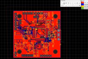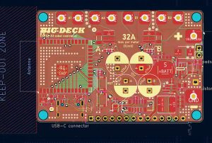

Drones are widely used in fields such as industrial inspection, surveying and mapping, agricultural plant protection, logistics, and emergency rescue. As flight control, navigation, communication, and onboard intelligent technologies continue to evolve, the requirements for precision, stability, and reliability in PCB assembly have become increasingly stringent.
Turnkey drone PCB assembly services integrate engineering design, component procurement, PCB manufacturing, SMT assembly, and quality inspection. This approach helps companies optimize manufacturing coordination, enhance product consistency, and improve delivery efficiency.
This article provides an in-depth analysis of key technologies and turnkey manufacturing solutions for drone PCB assembly, covering areas such as flight control hardware design, core assembly processes, quality control, and supply chain coordination.
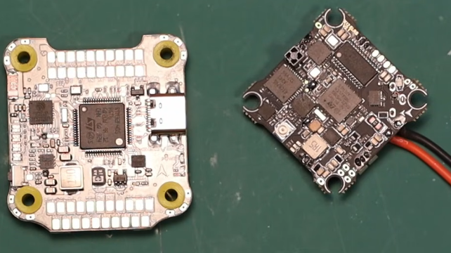
I. Why Is Drone PCB Assembly More Complex Than Standard Electronic Assembly?
Drone electronic systems are typically characterized by high integration, space constraints, high power density, and the coordination of multiple subsystems. While different types of drones vary in terms of mission payloads, propulsion structures, and communication methods, their core electronic hardware must consistently meet rigorous standards for electrical performance, mechanical reliability, and environmental adaptability.
Higher Hardware Stability Requirements for Flight Control Systems
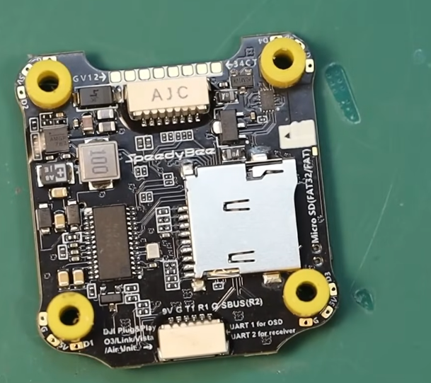
The flight controller serves as the central control unit of a drone. It generally integrates a microcontroller or application processor, an inertial measurement unit (IMU), a barometer, memory, communication interfaces, and power management circuitry.
Within this, the gyroscopes and accelerometers in the IMU provide critical measurement data for attitude estimation. Any defects in PCB layout, soldering, or mechanical mounting can lead to issues such as vibration coupling, localized stress, or power supply noise. These factors can degrade the quality of sensor measurements, thereby complicating the debugging of attitude estimation and control algorithms.
It should be noted that while flight stability is not determined solely by PCB assembly, consistency in PCB design and manufacturing is a fundamental prerequisite for ensuring reliable sensor data and a verifiable, repeatable control system.
Significant Power Integrity Challenges Posed by Propulsion Systems
The electronic speed controller (ESC), motors, and battery collectively form the drone’s propulsion system. Motor commutation, PWM switching, and rapid fluctuations in current can generate transient voltage spikes and electromagnetic interference (EMI). If the impedance of the power supply circuit is too high, decoupling capacitors are poorly placed, or there is insufficient isolation between high-current paths and sensitive analog circuits, it can lead to issues such as processor resets, sensor anomalies, communication errors, or even the overheating of power components.
Therefore, the quality of a drone’s PCB assembly cannot be judged solely by the appearance of solder joints or the correct placement of components; one must also consider the power distribution, grounding structure, and operational performance under actual load conditions.
The Engineering Trade-off Between Lightweight Design and Mechanical Reliability
Drones are highly sensitive to weight. However, indiscriminately thinning the PCB, reducing copper thickness, or shrinking the spacing between components can increase risks related to current-carrying capacity, heat dissipation, board warpage, and solder joint fatigue.
Power components, large connectors, shielding covers, and heavy inductors or capacitors are particularly susceptible to varying degrees of mechanical stress in high-vibration environments. Designers must take a holistic approach—considering component mass, placement, support methods, PCB thickness, and the vibration characteristics of the entire drone—rather than simply pursuing the smallest possible dimensions.
Different Drone Models Require Different Manufacturing Strategies
Consumer-grade aerial photography drones typically prioritize high integration, low weight, and consistency across mass production. Industrial drones focus more on long-duration operation, resistance to interference, and ease of maintenance. Agricultural drones, meanwhile, must account for heavy power loads, power supply stability, and the challenges posed by humid, dusty, or chemically active environments.
Consequently, a “one-stop” service does not imply that every project follows the exact same manufacturing process. A truly professional manufacturing partner should develop tailored engineering and quality control strategies based on the specific functions of various boards—such as flight controllers, electronic speed controllers (ESCs), navigation modules, communication boards, and mission payload boards.
II. What Does a One-Stop Drone PCB Assembly Service Actually Entail?
The core value of a one-stop service lies in the coordinated management of technical responsibilities and delivery stages—tasks that might otherwise be fragmented across multiple suppliers. This ensures that design requirements are consistently maintained throughout the entire lifecycle, encompassing material procurement, manufacturing, assembly, and verification.
Engineering Design Review and Design for Manufacturing (DFM) Analysis
Before production begins, the manufacturing engineering team must evaluate the PCB design files, Bill of Materials (BOM), coordinate files, assembly drawings, and all relevant process requirements. The focus is not merely on verifying that all files are present, but on identifying potential issues that the design might encounter during actual production—for example:
Ensuring that component footprints match the procured part numbers, and checking for any discrepancies in pin definitions or package dimensions.
Confirming that high-density BGA and QFN packages, as well as fine-pitch components, are compatible with assembly, soldering, and inspection requirements.
Determining whether large connectors, power inductors, or shielding cans require specialized soldering techniques or additional mechanical support.
Verifying that PCB edges, mounting holes, fiducial marks, and panelization designs are suitable for automated manufacturing.
Ensuring that test points are accessible to probes and that critical power rails can be measured independently.
Assessing risks related to long lead times, component obsolescence, or the availability of compatible alternatives for critical parts.
Design for Manufacturing (DFM) and Design for Testability (DFT) analyses should be conducted before full-scale production begins. For complex flight control boards, identifying issues with footprints, layout, or test design early on is generally far more cost-effective than attempting rework after production is complete.
Bare PCB Fabrication and Stack-up Control
A one-stop service provider can integrate bare PCB fabrication and subsequent assembly under a single quality management system. This encompasses processes such as multi-layer board fabrication, impedance control, surface finishing, drilling, plating, and circuit imaging.
Drone flight control boards often utilize multi-layer PCB structures to effectively organize high-speed digital signals, power distribution, and sensitive analog circuitry. For designs involving high-speed processors, high-speed memory, or high-frequency communication interfaces, impedance control requirements must be evaluated based on specific interface data rates, material properties, and routing configurations.
Acceptance of bare PCBs should go beyond a simple visual inspection. For critical projects, it is essential to verify specifications—such as board thickness, copper weight, hole-wall copper quality, layer-to-layer registration, solder mask integrity, and surface finish—alongside the results of necessary electrical tests.
Component Procurement and BOM Management
Drone PCB assembly typically involves a variety of components, including main control chips, inertial sensors, power management ICs, MOSFETs, power inductors, connectors, memory modules, and various passive components.
A one-stop service provider can handle centralized procurement, incoming material inspection, and production kitting based on the Bill of Materials (BOM), thereby reducing the risk of batch inconsistencies that can arise when sourcing from multiple suppliers. For core components of flight control systems, procurement management is of critical importance. Even if two components share the same package, it does not guarantee compatibility in terms of electrical parameters, register configurations, temperature ranges, startup sequences, or software drivers.
Any alternative component must undergo engineering review. Depending on the associated risk, this process should include sample verification, functional testing, and version documentation; components should never be substituted based solely on price, stock availability, or identical packaging.
SMT Assembly, Soldering, and Post-Processing
Surface Mount Technology (SMT) is a core process in the assembly of drone PCBs, encompassing solder paste printing, component placement, reflow soldering, and necessary post-processing steps.
For fine-pitch processors, QFNs, BGAs, and small passive components, soldering quality directly impacts the reliability of electrical connections. The production team must develop a reflow profile—factoring in pad design, component thermal capacity, PCB thickness, and solder paste characteristics—and validate its suitability through process testing.
If a product incorporates through-hole connectors, high-current terminals, or specialized shielding structures, additional methods such as selective soldering, manual touch-up, or other validated assembly techniques may be required.
Electrical Testing, Functional Verification, and Delivery Traceability
A comprehensive service does not end with component placement. Depending on the complexity of the product, further testing options include Automated Optical Inspection (AOI), X-ray inspection, In-Circuit Testing (ICT), flying-probe testing, power-on checks, functional testing, and the use of custom test fixtures.
For drone flight control boards, specific verification protocols can be established for areas such as sensor communication, power rails, clock signals, memory, debugging interfaces, and communication ports.
Data—including serial numbers, material batch information, production process versions, test results, and rework records—should be linked for each individual board. This ensures the ability to conduct quality analysis, batch tracking, and field failure diagnostics in the future.

III. Flight Control PCB Design: A Key Technology Determining the Upper Limit of Assembly Quality
High-quality PCB assembly relies on sound circuit design. If the design itself suffers from significant issues—such as poor signal integrity, power integrity, or mechanical structural flaws—simply increasing placement precision will not effectively resolve system failures.
IMU Placement and Vibration Coupling Control
The placement of the Inertial Measurement Unit (IMU) should be evaluated by considering the flight controller’s mounting location, the airframe’s vibration characteristics, and the sensor’s specific requirements.
Generally, the IMU should not be placed near high-vibration sources. Furthermore, careful attention must be paid to its proximity to large connectors, mounting points along the board edges, heavy components, and localized heat sources. There is no universal “fixed distance” for IMU placement that applies to all drones; the optimal position must be determined through structural analysis, vibration measurement, and flight testing.
Additionally, factors such as copper traces, vias, solder mask, and local PCB thickness beneath the sensor can influence thermal distribution and mechanical properties. During the layout phase, it is essential to ensure a robust structure, avoid localized stress concentrations, and follow the sensor manufacturer’s design recommendations for mounting.
It is important to note that adding soft padding or vibration-isolation structures does not guarantee improved measurement quality. Vibration-isolation systems have their own frequency response characteristics; if designed improperly, they can introduce new resonance peaks. Therefore, mechanical vibration isolation and digital filtering must be validated in tandem at the full-system level.
Power Integrity and High-Current Circuit Design
Power supply design for drone PCBs must account for load dynamics, conversion efficiency, transient response, and thermal management.
For processors, sensors, and wireless communication modules, power supply ripple and transient voltage drops must remain within the limits specified by the component datasheets and system design requirements. For motor drives, electronic speed controllers (ESCs), or other high-current modules, the current-carrying capacity of conductors must be evaluated based on continuous current, peak current, copper thickness, trace width, ambient temperature, and allowable temperature rise.
Key design considerations include:
Minimize the area of high-frequency switching loops to reduce parasitic inductance and voltage spikes.
Place decoupling capacitors as close as possible to the corresponding power pins, while controlling the parasitic parameters of the connection paths.
Plan appropriate return paths for sensitive analog circuits to ensure that high-current return flows do not interfere with measurement signals. Evaluate the temperature rise of copper traces based on actual current distribution and thermal simulation results, rather than relying solely on empirical estimates for trace width.
Incorporate test points on critical power rails to facilitate production testing and fault isolation.
If the switching node of a power converter is placed too close to an IMU, an ADC input, or a high-impedance analog signal, noise may be coupled via electric fields, magnetic fields, or common-impedance paths. Such issues require a comprehensive analysis covering layout, return paths, filtering, and shielding.
High-Speed Signals and Impedance Control
Some drone flight control systems incorporate high-speed memory, USB, high-speed serial interfaces, or high-frequency RF circuitry. These interfaces impose specific requirements regarding trace impedance, reference plane continuity, differential pair matching, and via structures.
During the manufacturing phase, it is essential to verify that the PCB stack-up, dielectric thickness, copper thickness, and material parameters align with the design assumptions. For controlled-impedance traces, define the test methods, test frequencies, and acceptance criteria based on project requirements, and incorporate these specifications into the bare-board manufacturing documentation.
While matching the lengths of differential traces is important, one should not mechanically pursue identical lengths without considering signal rise times, circuit topology, and interface specifications. Discontinuities in reference planes, via stubs, transitions at connectors, and interruptions in return paths can all lead to signal reflections and crosstalk.
RF Layout and Electromagnetic Compatibility (EMC)
Drones typically utilize a combination of remote control links, telemetry links, satellite navigation, Wi-Fi, or other wireless communication systems. The coexistence of multiple RF systems alongside high-speed digital circuitry increases the complexity of EMC design.
For RF PCBs, the layout should be developed by considering the operating frequency bands, antenna types, feed-line impedance, and manufacturer-provided reference designs. Key design checks must include antenna clearance zones, ground plane continuity, and the routing of RF connectors and feed lines.
Flight control processors, DC-DC converters, and high-speed digital signals can act as potential sources of interference; therefore, it is crucial to minimize noise coupling paths and conduct necessary EMC testing on the fully assembled system. When RF circuits and digital control circuits are integrated onto the same board, it is essential to evaluate the grounding strategies, shielding schemes, and power supply filtering for each module. One must be careful not to mistake localized optimizations for the achievement of system-level electromagnetic compatibility (EMC).
IV. Core Processes and Quality Control in UAV PCB Assembly
The quality of UAV PCB assembly depends on the synergy of multiple process parameters, rather than the precision specifications of any single piece of equipment. For high-reliability products, manufacturers must establish a repeatable process window and utilize inspection data to verify the stability of the process.
Solder Paste Printing: Ensuring Consistency at the Solder Joint Level
Solder paste printing is a critical stage in SMT assembly that directly influences soldering outcomes. Factors such as stencil aperture design, solder paste characteristics, squeegee parameters, PCB support methods, and pad design all affect the volume and consistency of the deposited solder paste.
For fine-pitch QFNs, BGAs, and high-density passive components, particular attention should be paid to risks such as insufficient or excessive solder, misalignment, bridging, and uneven printing. Where necessary, Solder Paste Inspection (SPI) should be employed to assess print volume, area, and offset, with the resulting statistical data used to refine stencil and printing parameters.
For components with thermal pads, solder paste coverage and aperture segmentation must be evaluated in conjunction with thermal management requirements and component specifications to prevent issues such as excessive voids, component floating, or solder overflow.
Reflow Soldering: Tailoring Temperature Profiles to Specific Components
The reflow soldering process requires a comprehensive approach, accounting for the heating rate, preheating, soak phase, peak temperature, time above liquidus, and the cooling phase.
Because different solder pastes, PCB thermal capacities, and component packages require distinct process windows, a “one-size-fits-all” temperature profile is not appropriate. During production validation, thermocouples should be used to monitor representative locations on the board, ensuring that both high-thermal-mass areas and heat-sensitive components remain within their respective optimal temperature ranges.
For designs involving large connectors, thick copper boards, or mixed-package configurations, special attention must be given to process risks arising from temperature differentials, solder joint wetting, and variations in thermal capacity. 3. BGA and QFN: Hidden Solder Joints Require Specialized Verification
Solder joints for BGA and certain QFN components cannot be fully inspected via standard visual checks. The absence of visible anomalies on the component surface does not guarantee that all solder joints meet the required specifications.
X-ray inspection can be used to identify issues such as solder bridging, voids, irregular solder balls, and other internal defects. However, its effectiveness is constrained by factors including package architecture, the nature of the defects, imaging conditions, and established acceptance criteria. For critical flight control boards, an X-ray inspection strategy—whether sampling-based or 100% inspection—should be developed based on component type, design risk, and customer acceptance requirements. Any anomalies detected must undergo professional engineering evaluation.
Furthermore, the assumption that a lower void ratio is always better does not apply universally. Acceptance criteria should be tailored to specific package types, pad functions, and thermal management structures. For instance, the thermal pads of high-power components require an assessment that balances thermal performance with reliability requirements.
Conformal Coating and Moisture Protection
Industrial drones often operate in environments characterized by high humidity, dust, significant temperature fluctuations, or corrosive contaminants. In such cases, a conformal coating can enhance the environmental protection of a PCB.
However, a conformal coating is not a substitute for robust enclosure design, connector sealing, or comprehensive system-level protection. Before application, it is essential to verify the absence of flux residue, ensure surface cleanliness, confirm material compatibility, and validate curing conditions. Additionally, a masking plan must be implemented to protect connectors, test points, sensor openings, heat-dissipating surfaces, and areas designated for future repair. For components that require direct environmental exposure—such as barometric pressure sensors, gas sensors, or similar devices—conformal coatings may adversely affect response times or measurement accuracy; therefore, the specific guidelines provided by the component manufacturer must be strictly followed.
Moreover, conformal coating is not mandatory for all drone PCBs. For designs prioritizing lightweight construction, ease of maintenance, or specific thermal management needs, the decision to apply a coating—as well as the selection of the appropriate material and application process—should be determined through an environmental risk assessment.
V. Material Management: High-Reliability Assembly Requires More Than Just Considering Purchase Price
In the electronics manufacturing of unmanned aerial vehicles (UAVs), the stability of the component supply chain directly impacts product consistency, R&D timelines, and after-sales risks.
Implement Differentiated Management for Critical Components
Components such as flight control processors, IMUs, GNSS-related modules, power management ICs, and power MOSFETs can significantly influence system performance. For these critical components, it is essential to verify the manufacturer, full part number, package type, temperature rating, product lifecycle status, and all relevant certifications or quality documentation.
Even for standard components like resistors and capacitors, one must not overlook differences in voltage ratings, precision, temperature coefficients, dielectric types, and package dimensions.
Within the Bill of Materials (BOM) management process, it is necessary to clearly define primary components, approved alternatives, and prohibited substitutes, while establishing a version control mechanism. Any substitution that could alter electrical performance or manufacturing processes must undergo a formal written review.
Regulated Control for Moisture-Sensitive Devices
Certain semiconductor packages are moisture-sensitive. If storage conditions, opening procedures, or exposure durations prior to reflow soldering do not meet the manufacturer’s specifications, it increases the risk of internal moisture absorption and damage during the soldering process.
Based on the component’s Moisture Sensitivity Level (MSL), packaging labels, and applicable standards, manufacturers must strictly manage dry storage, maintain records of when components are unsealed, monitor exposure duration, and perform necessary baking procedures.
Baking cannot be performed indefinitely, as some components, carrier tapes, trays, or packaging materials may not withstand repeated exposure to high temperatures. The correct approach is to follow the manufacturer’s specifications and relevant industry standards, rather than applying a uniform, fixed duration and temperature for all items.
Traceability Systems Must Cover Materials and Production Batches
When a UAV experiences issues in the field—such as intermittent resets, sensor anomalies, or power failures—failure analysis becomes difficult if the specific component batches and production conditions used for a given PCB cannot be identified.
Therefore, it is recommended to establish a traceability framework for critical products that links the following: PCB serial number, bare board batch, critical component batches, production date, process version, test results, and rework history. For high-value industrial drones, the serial number of the complete unit can be linked to the specific circuit boards (PCBs) installed within it. This traceability enables rapid identification of affected units in scenarios such as supplier changes, quality anomalies, or field repairs.
VI. How should a drone be verified after PCB assembly?
The completion of the manufacturing process does not necessarily mean the product is ready for final delivery. Quality inspections at the PCB level, functional verification at the board level, and environmental testing of the complete unit serve distinct purposes; these should be combined appropriately based on the product’s risk profile.
Visual and Solder Quality Inspection
Automated Optical Inspection (AOI) can be used to detect missing or misaligned components, polarity errors, visible solder joint defects, and printing issues. For hidden solder joints, appropriate methods—such as X-ray inspection—should be employed based on the component’s structure.
The inspection protocol must clearly define defect classifications, acceptance criteria, and re-inspection procedures. For critical defects, a board should not be deemed “acceptable” simply because it passes a visual check after rework; it must also undergo electrical re-testing, with the scope determined by the associated risk.
Power and Interface Testing
Before powering on, perform essential checks for short circuits, verify power inputs, and confirm correct polarity. Once powered on, measure key power rails, current consumption, startup status, and signals at critical interfaces.
For flight control boards, test cases can be developed for the following functions:
Main controller startup, firmware identification, and communication via debug interfaces.
Identification and data acquisition from sensors such as the IMU and barometer.
Basic functionality of memory, clock circuits, and essential peripherals.
Communication status of interfaces such as UART, SPI, I²C, CAN, or others specific to the actual hardware configuration.
Output voltage, ripple, and temperature rise of power converters under specified load conditions.
System reset, protection, and recovery behavior during critical fault conditions.
Test content should be tailored to the actual hardware configuration; boards should not be expected to support interfaces that are not part of their specific design.
Vibration, Temperature, and Environmental Reliability Verification
For industrial-grade or high-reliability drones, it is advisable to evaluate the need for environmental testing—such as temperature cycling, vibration, shock, or damp-heat testing—based on the intended operating environment and the product’s risk assessment. Vibration testing should go beyond checking for physical damage to the PCB; it must also account for issues such as loose connectors, solder joint fatigue, sensor data drift, and intermittent communication failures.
Temperature testing should focus on cold-start performance, operation at full load under high temperatures, functional changes following thermal cycling, and the temperature rise of critical components. Test conditions must be derived from product specifications, the intended operational environment, and applicable standards, rather than relying on arbitrary, one-size-fits-all temperature ranges or vibration parameters.
For flight control systems, environmental testing must be followed by comprehensive functional re-verification to ensure that the hardware continues to meet its original performance requirements.
Board-Level Verification Cannot Replace Full-System Verification
Passing electrical tests at the PCB level does not guarantee stable operation once the board is integrated into the final assembly. Full-system integration can introduce new challenges, such as motor-induced vibration, battery voltage drops, antenna interference, altered thermal conditions, and mechanical stress on connectors.
Therefore, professional projects should employ a tiered verification framework: board-level testing to confirm basic circuit functionality; subsystem testing to examine interfaces and coordination between modules; and full-system testing to evaluate overall performance under real-world operating conditions.
For products related to flight control or propulsion, functions critical to flight safety must undergo rigorous ground-based verification, followed by systematic, incremental testing in appropriate and safe environments.
VII. How to Choose a Truly Professional, One-Stop PCB Assembly Supplier for Drones?
The value of a one-stop service provider lies not in the number of processes they advertise, but in their ability to understand the specific hardware requirements of drones, manage manufacturing risks, and consistently deliver high-quality, compliant products.
Evaluate the Engineering Team, Not Just the Production Equipment
Possessing high-speed pick-and-place machines, reflow ovens, and Automated Optical Inspection (AOI) equipment merely indicates a baseline production capability; it does not prove that a supplier is well-suited for complex drone projects.
It is essential to assess whether the supplier possesses expertise in areas such as engineering reviews for multi-layer boards, BGA and QFN assembly processes, controlled-impedance manufacturing, power and thermal design analysis, and the development of custom test fixtures.
For projects involving Inertial Measurement Units (IMUs), high-speed interfaces, or high-current circuits, you should also verify that the supplier understands the relevant design constraints and can translate them into actionable manufacturing and inspection requirements. 2. Evaluating Quality Systems and Data Transparency
Suppliers should be capable of providing quality records relevant to the project, including documentation for incoming material inspections, production batches, weld/solder joint inspections, functional testing, and the handling or rework of non-conforming products.
If a project entails requirements specific to the automotive, aerospace, or other specialized industries, it is essential to verify the scope of the supplier’s certifications, the applicable product categories, and the specific manufacturing locations covered. The mere possession of a certification by a supplier does not automatically guarantee that every product or every process step meets the associated requirements.
Evaluating Supply Chain and Change Management Capabilities
During the prototyping phase, a component shortage might only affect a small number of test boards; however, in mass production, an unauthorized component substitution could compromise performance consistency across multiple batches.
Key areas to assess include the supplier’s ability to manage lifecycle risks, identify long-lead-time components, provide traceable procurement data, and implement a formal change approval process in the event of material shortages.
Any changes involving critical components, PCB materials, stack-up structures, soldering/welding processes, or testing methodologies must be evaluated and validated based on the extent of their potential impact.
Evaluating Mass Production Ramp-up and Continuous Improvement Capabilities
Professional manufacturing service providers must employ distinct strategies tailored to each project phase. The early prototyping stage focuses on the rapid resolution of engineering issues; the design verification stage centers on confirming key performance and reliability metrics; and the mass production stage prioritizes process stability, batch-to-batch consistency, delivery capacity, and defect rate trends.
During the evaluation, one should ask the supplier to explain their approach to first-article inspection, trial production issues, root cause analysis, corrective and preventive actions (CAPA), and continuous improvement throughout the mass production lifecycle.
Rather than simply comparing the lowest quoted price, it is far more valuable to determine whether a supplier can minimize rework and hidden quality costs through engineering collaboration, while ensuring a seamless and reliable manufacturing transition during product upgrades.
VIII. From Prototype to Mass Production: Establishing a Scalable Manufacturing System
A common risk in drone projects is that a design may function perfectly during the prototyping phase, only to encounter issues—such as soldering inconsistencies, component batch variations, or divergent test results—once it moves into mass production.
To mitigate these risks, the manufacturing strategy must evolve in tandem with the product’s maturity.
Prototyping Phase: Rapid Validation of Design Assumptions
The prototyping phase should prioritize the validation of key design assumptions, including the selection of critical components, PCB stack-up, power delivery architecture, sensor interfaces, and high-speed signal integrity.
During this stage, the manufacturing partner should assist the R&D team in identifying potential design-for-manufacturing (DFM) issues, while ensuring that sufficient test points and debugging interfaces are incorporated. For unverified component alternatives, specialized soldering structures, or complex packaging, risks must be clearly documented; it is premature to codify unproven processes as standards for mass production.
Design Verification Phase: Focusing on Boundary Conditions
As the project enters the design verification phase, the focus shifts to evaluating product performance across its intended operating range. This includes assessing power supply dynamic response, temperature rise under full load, communication stability, sensor measurement accuracy, and environmental adaptability.
Test results should be fed back into the PCB design and process documentation, with updates made—where necessary—to the stack-up, component placement, pad design, or testing specifications.
If the product requires Design Verification Testing (DVT), the test plan must clearly define sample sizes, test conditions, failure criteria, and the standards for resolving issues. Relying on a small number of successful prototypes to infer the reliability of mass-produced units should be avoided.
Mass Production Phase: Controlling Process Variability
The key to mass production lies in ensuring consistency across batches—in terms of materials, manufacturing processes, and test outcomes.
Depending on the scale of the project, the manufacturing team may employ methods such as first-article inspection, in-process sampling, monitoring of critical parameters, statistical process control (SPC), and periodic process audits. For recurring issues—such as soldering defects, functional anomalies, or the need for rework—a root-cause analysis and a corrective/preventive action (CAPA) mechanism should be established, rather than relying on manual screening to maintain shipment quality.
Furthermore, it is essential to maintain controlled versions of the Bill of Materials (BOM), Gerber files, assembly documentation, test programs, and process specifications, ensuring that every production batch utilizes only approved technical data. IX. The True Value of One-Stop Service: Mitigating Systemic Manufacturing Risks
For drone manufacturers, the cost of PCB assembly should not be viewed merely as the sum of bare-board prices and component placement fees. Factors such as material management, engineering reviews, test development, rework, delivery fluctuations, and post-sales failures all contribute to the final product cost.
When PCB fabrication, component procurement, assembly, and testing are fragmented across multiple suppliers, gaps can emerge regarding design file versions, quality standards, and accountability. A one-stop service model reduces coordination overhead and ensures that any manufacturing anomalies can be more easily analyzed along a unified delivery chain.
It should be noted, however, that “one-stop” does not necessarily mean every single process must be performed in-house by a single factory. A well-structured outsourcing ecosystem can also deliver high-quality results, provided there are clearly defined responsibilities, full process traceability, consistent technical requirements, and effective management of outsourced operations.
When selecting a service model, companies should prioritize the following criteria:
Engineering Responsiveness: The ability to promptly address DFM (Design for Manufacturing) issues, design changes, and manufacturing anomalies.
Quality Stability: The ability to consistently meet agreed-upon inspection standards and product specifications.
Supply Chain Resilience: The ability to mitigate risks such as shortages of critical components, product obsolescence, or the use of unauthorized substitutes.
Test Coverage: The ability to establish repeatable verification protocols for key functionalities.
Batch Traceability: The ability to link product serial numbers and material batches to specific production records and test results.
Scalability for Mass Production: The ability to ensure a smooth transition from engineering prototypes to sustained, large-scale production.
Collectively, these capabilities determine whether a one-stop drone PCB assembly provider can truly serve as a long-term partner within a company’s product R&D and manufacturing ecosystem.
X. Conclusion
Drone PCB assembly integrates precision manufacturing, electronic design, and quality verification—with every stage directly impacting the stability of the flight control system and the overall reliability of the drone.
KingTop Technology offers a one-stop drone PCB assembly solution, emphasizing engineering collaboration, manufacturing excellence, and quality traceability. We help companies shorten R&D cycles and optimize production efficiency, ensuring reliable delivery from prototype development through to mass production. As drone technology continues to evolve, KingTop Technology is dedicated to providing professional support for the manufacturing of drone electronic hardware, helping clients enhance the competitiveness of their products.