As the global automotive industry undergoes a profound transformation toward electrification, intelligence, and connectivity, automotive electrical and electronic architectures are shifting from distributed systems to domain control and central computing.
This evolution has positioned automotive-grade printed circuit board assemblies (PCBAs) as a critical hub for overall vehicle reliability.
Unlike consumer electronics, which prioritize miniaturization and rapid iteration, automotive-grade PCBAs must withstand extreme operating environments—ranging from the high heat and humidity of the engine compartment and the continuous mechanical vibrations of the chassis to frequent transient voltage surges and exposure to harsh chemicals.

Even a minute void in a solder joint or insufficient insulation spacing can trigger a vehicle-level failure, potentially endangering the lives of occupants.
Consequently, establishing a full-lifecycle quality control system—spanning design, manufacturing, and packaging through to final acceptance—to achieve true “Zero Defect” design and manufacturing has become a key competitive benchmark in the high-end intelligent manufacturing sector.
Leveraging a 10,000-square-meter modern cleanroom facility and over ten fully automated SMT production lines, KingTop Technology specializes in the manufacturing and rigorous acceptance testing of automotive-grade PCBAs. We strictly adhere to the IATF 16949 quality standard and utilize advanced inspection technologies—including 3D SPI, 3D AOI, and AXI (non-destructive testing)—alongside rigorous DFM reviews, precision reflow soldering, and multi-dimensional environmental reliability testing to ensure high reliability and “Zero Defect” quality.
I. Quality Systems and Design Guidelines (DFM/DFT) for Automotive-Grade PCBAs
IATF 16949 and the “Zero Defect” Management Philosophy
The manufacturing of automotive-grade PCBAs is far more than standard contract manufacturing; the entire production process must strictly comply with the IATF 16949 automotive quality management system certification. This system is centered on a process-oriented approach, emphasizing risk-based thinking and comprehensive supply chain traceability.
APQP (Advanced Product Quality Planning): At the initial stage of project introduction, a cross-functional team (comprising process, quality, test, and manufacturing engineering) must be established. Through multi-party validation, the team ensures that manufacturability and testability are incorporated into the product during the design phase.
FMEA (Failure Mode and Effects Analysis): DFMEA and PFMEA are conducted across the entire process—covering PCB design, component selection, SMT placement, and soldering—to precisely identify potential risk points and establish stringent RPN (Risk Priority Number) control thresholds.
SPC (Statistical Process Control) and MSA (Measurement System Analysis): In the manufacturing stage, real-time SPC monitoring must be implemented for critical process parameters—such as print thickness, SMT placement offset, and reflow oven temperature profiles—to ensure a process capability index (Cpk) of ≥ 1.33, or even ≥ 1.67.
DFM (Design for Manufacturability) Standards for Harsh Environments
A comprehensive DFM review prior to the start of production is fundamental to ensuring high yields. DFM guidelines for automotive-grade designs must not only meet standard IPC requirements but also incorporate stricter design measures to withstand the specific physical stresses encountered in automotive applications:
Pad and Solder Mask Design: For high-power components (e.g., MOSFETs, IGBTs), arrays of thermal vias must be designed around the pads. Processes such as resin plugging or copper-filled via plating must be employed to prevent solder paste from leaking through via openings during reflow soldering, which could otherwise lead to voiding.
Component Spacing and Safety Distances: To account for humidity, condensation, and transient high-voltage conditions in automotive environments, electrical clearance and creepage distances between high-voltage and low-voltage components must comply with ISO 26262 and relevant functional safety standards; anti-creepage slots must be added where necessary.
Panelization and Manufacturing Edge Design: Automotive-grade boards often feature complex structures and significant weight. Robust manufacturing edges and V-cut or routed breakaway tabs (with perforated bridges) must be designed during panelization, alongside strategic fiducial mark placement, to prevent mechanical deformation during high-speed component placement and board transport.
Thermal Design and Stress Simulation Analysis
Automotive-grade PCBAs frequently incorporate high-power chips, making thermal failure one of the primary physical failure modes.
Finite Element Analysis (FEA) Thermal Simulation: During the PCB layout phase, multi-physics simulation software must be employed to model the temperature distribution across the entire board under maximum load. This identifies “hot spots” and guides the optimized placement of heat sinks, thermal interface pads, and large copper pour areas.
Mechanical Stress Simulation: This simulates PCB bending and deformation caused by road vibrations and bumps during vehicle operation. It evaluates the fatigue life of solder joints for rigid packages—such as BGAs, QFNs, and connectors—under cyclic mechanical stress (predicted using the Coffin-Manson model).
II. Technical Requirements for Automotive-Grade PCB Substrates and Surface Finishes
Selection of High-Reliability Substrates (High Tg, Low CTE, CAF Resistance)
The substrate serves as the physical structural backbone of the PCBA; automotive environments demand exceptional physical stability and chemical inertness.
High Glass Transition Temperature (High Tg): Automotive-grade PCBs typically require a Tg of ≥ 170°C (or higher) to ensure the substrate does not soften or expand in high-temperature operating environments, thereby preventing delamination or via barrel cracking.
Low Coefficient of Thermal Expansion (Low CTE): The Z-axis CTE must be sufficiently low to minimize fatigue fractures in via barrel copper caused by tensile stress during extreme temperature cycling (e.g., -40°C to +125°C or higher).
CAF (Conductive Anodic Filament) Resistance: In environments characterized by high voltage, high humidity, and DC bias, copper ions can easily migrate along glass fiber bundles, potentially creating microscopic short circuits. For automotive-grade PCBs, specialized laminates with high CAF (Conductive Anodic Filament) resistance must be selected, and the minimum safe hole-to-hole spacing must be increased.
Surface Finish Selection and Failure Prevention
The surface finish directly determines solder joint wettability as well as long-term oxidation and corrosion resistance.
ENIG (Electroless Nickel/Immersion Gold): Offers excellent flatness, making it ideal for fine-pitch BGAs and miniature components. However, the phosphorus content in the nickel layer must be strictly controlled (typically between 7% and 9%), and the “Black Pad” phenomenon must be closely monitored to prevent brittle solder joint fractures caused by excessive nickel corrosion.
ENEPIG (Electroless Nickel/Electroless Palladium/Immersion Gold): A premium surface finish that introduces a palladium barrier layer, completely eliminating the “Black Pad” risk associated with ENIG. It offers superior wire bonding capabilities and withstands multiple reflow cycles, making it the preferred choice for high-end automotive electronics (such as ADAS domain controllers and intelligent driving sensors).
OSP (Organic Solderability Preservative): Offers a flat surface and moderate cost; however, due to limited thermal cycling resistance and a tendency to oxidize after multiple reflow cycles, it is rarely used for automotive-grade multilayer boards or complex assemblies. If used, exposure time to air and environmental temperature/humidity must be strictly controlled.
Compatibility Control: Solder Mask and Conformal Coating
Solder Mask: Must exhibit excellent chemical resistance, insulation resistance, and blister resistance, capable of withstanding high-temperature leaded or lead-free reflow soldering without discoloration or delamination.
Conformal Coating Synergy: The surface energy of the solder mask must perfectly match the subsequently applied conformal coating (acrylic, polyurethane, silicone, or fluorocarbon resin) to prevent defects such as fish-eyes (pinholes), delamination, or uneven coverage at the edges.
III. Core Aspects of SMT Assembly and Soldering Process Control
Solder Paste Printing Precision Control and 3D SPI (Solder Paste Inspection)
70% of SMT soldering quality depends on solder paste printing; automotive-grade manufacturing allows for no negligence at this stage.
Stencil Design Optimization: Electropolished nano-stencils are utilized for fine-pitch components and high-power pads, combined with step-stencil technology to precisely control solder paste release volume.
3D SPI Full Inspection: High-precision 3D Solder Paste Inspection (SPI) equipment must be installed inline after the printer to conduct 100% inspection of solder paste volume, height, area, and offset. This enables the timely detection of defects such as insufficient paste, excessive paste, bridging, and slump, while providing real-time data feedback to the upstream printer for closed-loop compensation.
High-End Pick-and-Place Machine Parameter Optimization and Micro-Component Soldering
Automotive-grade PCBAs feature a dense distribution of components ranging from 01005 micro-resistors and capacitors to large-scale BGA and PoP packages.
Placement Pressure and Speed Control: For fragile ceramic capacitors (MLCCs), pick-and-place machines must be configured with precise placement heights and pressure profiles. This prevents excessive mechanical stress from causing internal micro-cracks in MLCCs—a primary cause of latent leakage or short circuits in automotive electronics during later stages of operation.
Odd-form Component Handling: For heavy connectors, transformers, and similar parts, multifunctional placement machines equipped with custom nozzles or robotic grippers are used to ensure micron-level placement accuracy.
Reflow Profile Optimization and Nitrogen Protection Mechanism
Scientific Temperature Zone Configuration: Forced hot-air reflow ovens with multiple temperature zones (e.g., 10 zones or more) are employed. The preheat zone must ensure sufficient solvent evaporation and a gradual heating rate (typically controlled at 1–2°C/s) to prevent solder paste spattering or thermal shock; the soak zone allows the flux to fully activate and remove oxides; and the reflow zone (peak zone) requires strict control of the peak temperature (typically 235–245°C for lead-free processes) and the time above liquidus (TAL, typically 60–90 seconds).
Nitrogen (N₂) Protection: Introducing high-purity nitrogen (maintaining oxygen concentration below 100 ppm) into critical reflow zones significantly reduces the oxidation rate of pads and solder powder, greatly improves solder joint wettability, lowers voiding rates, and enhances both the luster and mechanical strength of the solder joints.
| Process Step | Key Control Parameters & Metrics | Automotive-Grade Strict Standards |
| Solder Paste Printing | Volume Deviation, Height Deviation | Cpk ≥ 1.33, 100% 3D SPI Monitoring |
| Reflow Soldering | Peak Temperature, TAL Time, Cooling Rate | Cooling Rate 2 – 4°C/s, Lead-Free Solder Joints Full and Bright |
| BGA Soldering | Voiding Rate | Single Solder Joint Voiding Rate < 10% – 15% (Critical Power / High-Frequency Chips) |
IV. Special Processes and Assembly Challenges for Automotive-Grade PCBA
Underfill and Conformal Coating Processes
Automotive electronics are frequently subjected to severe vibration; therefore, underfill processes are mandatory for large-format BGA and CSP components, as well as high-density QFN chips.
Capillary Underfill: Low-viscosity, high-flowability epoxy resin is used to penetrate precisely beneath the chip via capillary action. Upon curing, it forms a robust stress-buffering layer that distributes shear stress—caused by the mismatch in coefficients of thermal expansion (CTE) between the chip and the PCB—thereby exponentially enhancing resistance to drop impact and vibration fatigue.
Selective Conformal Coating: Fully automated selective coating machines are employed to apply the coating while precisely avoiding sensitive areas on the PCBA surface (such as high-voltage connector pins and delicate sensors). This ensures a uniform coating thickness (typically 30–75 μm) that is UV-traceable (containing fluorescent agents) and free from bubbles or material accumulation.
Precision Assembly of Power Devices and Thermal Management Modules
The “Three-Electric” systems (VCU, MCU, and BMS) in new energy vehicles incorporate a large number of power semiconductors.
TIM (Thermal Interface Material) Application: The application of thermal grease, phase-change materials, or thermal pads must be uniform and bubble-free. High-precision dispensing robots or automated placement equipment are used to minimize interfacial thermal resistance and prevent localized overheating that could lead to thermal runaway.
Fastening Torque Control: Smart electric wrenches with torque monitoring capabilities are required for the screws securing power modules to heat-dissipating baseplates. This ensures balanced clamping pressure, preventing localized PCB warping or mechanical stress that could cause semiconductor chips to crack.
Stress Control for Odd-form Components and PCB Depaneling
Innovation in Depaneling Methods: Traditional stamping or manual snap-off depaneling methods are strictly prohibited. High-precision laser routers or milling routers must be used; these employ non-contact or low-stress cutting techniques to reduce the mechanical shock transmitted to surrounding sensitive components (such as chip capacitors and crystal oscillators) during the depaneling process to virtually zero.
V. Rigorous Testing and Acceptance Standards for Automotive-Grade PCBA (IPC-A-610 Class 3)
3D AOI, AXI (X-ray Inspection), and Void Ratio Control
Internal defects in automotive-grade PCBA cannot be detected by the naked eye; reliance on advanced non-destructive testing equipment is mandatory.
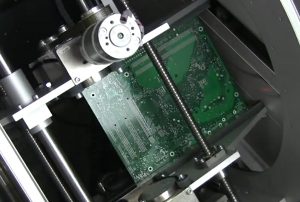
3D AOI (Automated Optical Inspection): Combines artificial intelligence with multi-angle structured light illumination to perform 3D scanning of components across the entire board, checking for polarity, incorrect parts, missing parts, standing components, lifted components, and solder joint appearance.
3D AXI (X-ray Inspection): Performs 100% tomographic scanning of hidden solder joints beneath BGA, LGA, and QFN packages, as well as power devices. The automotive industry enforces extremely strict specifications regarding void ratios; the IPC-A-610 Class 3 standard stipulates that the total area of voids within a single solder joint must not exceed 10% to 15% of the joint’s projected area. Exceeding this limit significantly increases the risk of excessive thermal resistance and mechanical cracking under conditions of high heat flux density.
| Inspection Technology | Inspection Target | Core Defect Types Caught |
| 3D SPI | Post-Printing Solder Paste | Insufficient Solder, Excessive Solder, Bridging, Slumping, Offset |
| 3D AOI | Post-Soldering Surface | Wrong Component, Missing Component, Polarity Reversal, Cold Joint, Tombstoning |
| 3D AXI | Hidden Solder Joints (Internal) | BGA Voiding, Bridging, Insufficient Ball, Internal Bubbles |
Electrical Performance Testing and In-Circuit Testing (ICT / FCT)
ICT (In-Circuit Testing): Uses a bed-of-nails fixture to contact PCBA test points and perform static parameter tests on components—such as impedance, capacitance, inductance, diodes, and transistors—to rapidly screen for short circuits, open circuits, and component failures.
FCT (Functional Testing): Simulates real-world automotive operating conditions by applying operating voltages and control signals to the PCBA. It performs fully automated, comprehensive functional testing of dynamic logic, communication protocols (e.g., CAN, LIN, FlexRay, Ethernet), and analog data acquisition accuracy, ensuring the product fully meets design specifications upon leaving the factory.
Programming & Calibration: Firmware programming and high-precision sensor parameter calibration are performed concurrently during the testing phase, ensuring 100% synchronization between hardware and software states.
Environmental Reliability Testing (Environmental Stress Testing)
Type testing prior to mass production and environmental sampling during mass production serve as the final checkpoints for verifying automotive-grade quality.
Thermal Shock / Cycling: Subjects the PCBA to hundreds of cycles in a chamber with rapid temperature fluctuations ranging from -40°C to +125°C (or higher), testing the limits of solder joints and substrate materials regarding thermal stress tolerance.
Vibration & Mechanical Shock: Simulates random vibration profiles encountered during high-speed driving, traversing speed bumps, and navigating harsh road conditions to verify the fatigue resistance of structural components and solder joints.
High Humidity & Salt Spray Testing (Combined Temperature/Humidity Cycling and Salt Spray Corrosion): Evaluates the electrochemical corrosion resistance of conformal coatings and exposed metal surfaces in coastal areas, high-humidity environments, or regions where de-icing agents are used.
Through the comprehensive implementation of these measures—ranging from strict control at the material source and rigorous closed-loop manufacturing processes to final comprehensive inspections and environmental stress screening—automotive-grade PCBAs can deliver the high reliability and “zero-defect” performance required by the extremely demanding automotive industry ecosystem.